- Catalogs
- SMC PNEUMATIC
- EX245 Series
EX245 Series
1 /12Pages

EX245 Series
1 /12Pages
Catalog excerpts

Integrated input-output type Fieldbus System (For Input/Output) EX245 Series ■ AIDA*1 specifications compliant ■ Push Pull connectors • One-touch installation and removal • Reduced wiring time Push Pull connectors C€ RoH IP65 Digital input modules Digital output module Compatible Protocols ■ Modules can be combined flexibly. • Number of valves, digital inputs/outputs Solenoid valve • Fiber-optic cable (SCRJ connector) • I/O modules can be connected and removed one by one. • Up to 8 modules can be connected in any order. Manifold Solenoid Valves SY3000/5000/7000 _l edAj_11 Z edAj 11_£ edAj_| |_I. edAj_11 Z edAj |
Open the catalog to page 1
EX245 Series Dual communication and dual power connectors Dual communication connectors allow daisy chain or ring topology for Media Redundancy Protocol (MRP). Dual power connectors allow for daisy chain connections avoiding branch or splitter adapters, saving cost and reducing wiring. To power supply Power supply cable Fiber-optic cable An external branch connector is not necessary. Reduced wiring space Easy to use one touch AIDA Push Pull connectors (compliant with AIDA specifications) saves time when installing and maintaining. Fiber-optic cable maintenance alarm This feature continuously...
Open the catalog to page 2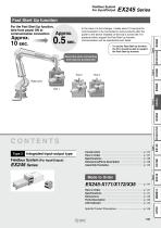
Fast Start Up function For the Fast Start Up function, time from power ON to communication connection Approx. 10 sec. Fieldbus System For Input/Output EX245 Series In the case of a tool changer, it takes about 10 seconds for communication to be connected in some products after the power to the device installed on the tool is turned ON. For products which support the Fast Start Up function, communication can be operational even faster. Save time when connecting and improve productivity To use the Fast Start Up function, the PLC should be able to support the Fast Start Up function. Integrated input-output...
Open the catalog to page 3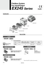
Fieldbus System For Input/Output Digital Input Module EX245-DX1 EX245-EA2- Digital input module specification DX1 Digital input (16 inputs) Digital Output Module Digital output module specification DY1 Digital output (8 outputs) * Please contact SMC for manifold valve part numbers.
Open the catalog to page 4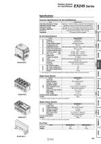
Fieldbus System For Input/Output EX24o Series Common Specifications for All Units/Modules *1 The setting file can be downloaded from the SMC website, http://www.smcworld.com Digital Input Module *1 An M12 (4-pin) connector can also be connected. Digital Output Module *1 An M12 (4-pin) connector can also be connected. _f edAj_11 Z edAj 11_£ edAj_| |_f edAj_11 Z edAj |
Open the catalog to page 5
Digital Input ModuleDigital Output Module EX245-DY1
Open the catalog to page 6
Fieldbus System For Input/Output Assembly Examples The modules and manifold valve are not assembled at the time of shipment. After assembling the SI unit and manifold valve, assemble the modules. Please contact SMC for order numbers. EX245-SPN1 EX245-DX1 EX245-DY1 EX245-EA2-1 Manifold valve Manifold valve Digital input module Manifold valve SI unit Digital module (Input) Digital module (Output) End plate Digital output module Joint∗2 End plate (With bracket) *1 Hexagon wrench is not included. It should be provided by the customer. *2 Joint and modular adapter are shipped together with...
Open the catalog to page 7
*1 Please contact SMC for the setting file.
Open the catalog to page 8
09ZX3 9znmimn oosxa oo9xa oszxa zzmzwzm onxa ostxa otsxa zuai/siai xaiv _V edAj_11 Z edAj 11_£ edAj_| |_l edAj_11 Z edAj |
Open the catalog to page 9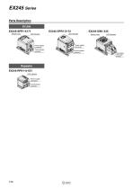
EX245 Series Parts Description SI Unit EX245-SPR1-X171 Switch cover Power supply connector Communication connector Repeater EX245-RPN1-A-X51 LED Indicator Power supply connector Communication connector Switch cover Power supply connector Communication connector Communication/ Power supply connector
Open the catalog to page 10
LINK: Communication state US1: Input/Power supply for control LINK: Communication connection state ACT: Data exchange FO: Communication diagnosis SF: System state BF: Communication state US1: Input/Power supply for control US3: External power supply 1 US4: External power supply 2 US4: External power supply 2 US2: Output/Power supply for valve US3: External power supply 1 US2: Output/Power supply for valve IB DIAG: INTERBUS diagnosis RC: Communication cable check RD: Communication state F01: BUS IN connection state F02: BUS OUT connection state US2: Output/Power supply for valve US3: External...
Open the catalog to page 11
EX245 Series Specific Product Precautions Be sure to read this before handling the products. Refer to page 277 for safety instructions. For fieldbus system precautions, refer to pages 278 to 280 and the “Operation Manual” on the SMC website: http://www.smcworld.com Operating Environment Caution 1. elect the proper type of enclosure according to the S operating environment. IP65 is achieved when the following conditions are met. 1) Provide appropriate wiring of the electrical wiring cables, communication connectors, and cables with M12 connectors. 2) uitable mounting of the SI unit, each module,...
Open the catalog to page 12All SMC PNEUMATIC catalogs and technical brochures
 Vacuum Unit 2024
99 Pages
 Air Cylinder CJ2 Series
117 Pages
 AS-FS Series
36 Pages
 IDF series
12 Pages
 MHL2 Series
24 Pages
 JCM Serie
18 Pages
 Pin Cylinder CJP2/CDJP2/CJP
19 Pages
 5 Port Solenoid Valve VQC
63 Pages
 5 Port Solenoid Valve VQ
79 Pages
 SY
SY268 Pages
 5-p0979-0980-hep500
2 Pages
 5-p0977-0978-aep100
2 Pages
 5-p0966-0971-lmu
5 Pages
 5-p0960-0966-alb900
6 Pages
 5-p0956-0960-ald600
5 Pages
 5-p0948-0950-al800
3 Pages
 es70-44c-vx2
52 Pages
 es50-37-kq2
124 Pages
 ex-pcw
23 Pages
 1-p2124-2152-ex510
29 Pages
 1-p2111-2122-ex500
12 Pages
 1-p2063-2073-ex260
11 Pages
 4-p0147-0178-msu-mds
32 Pages
 es20-230b-crb2
59 Pages
 1-p1869-1878-vp3145
10 Pages
 VP300/500/700 series
42 Pages
 1-p1789-1829-vqz100
41 Pages
 1-p1727-1788-syj300
62 Pages
 5 Port Solenoid Valve S0700
111 Pages
 5 Port Solenoid Valve VF
59 Pages
 5 Port Solenoid Valve SV
127 Pages
 VH
VH9 Pages
 CUJ
CUJ41 Pages
 AL
AL3 Pages
 kj mm
kj mm9 Pages
 AQ
AQ4 Pages
 SY3000/5000-X13
2 Pages
 Series MB
24 Pages
 Series LES
23 Pages
 Series LEFB
16 Pages
 Series PF3W
28 Pages
 Series IDG?A/IDG
56 Pages
 Floating Joint
7 Pages
 Series IZS40/41/42
32 Pages
 Series LEY
7 Pages
 Series VHS
12 Pages
 Series CY1S
28 Pages
 SeriesCQ2/CQS/CQ
4 Pages
 In-line Air Filter
12 Pages
 5 Port Solenoid Valve
60 Pages
 Series CQ2/CQS
2 Pages
 AS series
2 Pages
 corporate guide
13 Pages
 ZP
ZP69 Pages
 ZFA
ZFA14 Pages
 ZA
ZA13 Pages
 MHF
MHF32 Pages
 MHZ
MHZ68 Pages
 CRB
CRB44 Pages
 D
D117 Pages
 RB
RB23 Pages
 CEP
CEP44 Pages
 RSK
RSK30 Pages
 CLK
CLK51 Pages
 MK
MK20 Pages
 GLJ
GLJ65 Pages
 MGJ
MGJ7 Pages
 Mx
Mx36 Pages
 MXH
MXH18 Pages
 My3
My356 Pages
 my1b
my1b20 Pages
 CC
CC15 Pages
 J
J14 Pages
 CQ2
CQ251 Pages
 standard cylinder
84 Pages
 VFN
VFN6 Pages
 SY3000
246 Pages
 SJ3A6
SJ3A618 Pages
 1301/IW
14 Pages
 CHQ/CHDQ
19 Pages
 AC
AC95 Pages
 HAW
HAW4 Pages
 HAA
HAA3 Pages
 ZB
ZB24 Pages
 CRB2
CRB235 Pages


Archived catalogs
 CJ1
CJ15 Pages
 SYJ
SYJ62 Pages
 SJ
SJ78 Pages
 Vacuum Unit ZK2 Series
60 Pages
 SYJ300/500/700 Series
62 Pages
