D
1 /117Pages

D
1 /117Pages
Catalog excerpts

Auto Switch Guide Applicable Cylinder Series 1
Open the catalog to page 1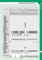
Applicable Cylinder Series 1
Open the catalog to page 2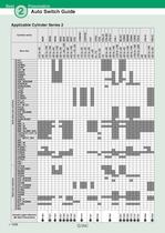
Auto Switch Guide Applicable Cylinder Series 2
Open the catalog to page 3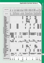
Applicable Cylinder Series 2
Open the catalog to page 4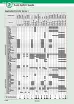
Auto Switch Guide Applicable Cylinder Series 3
Open the catalog to page 5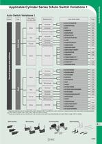
Applicable Cylinder Series 3/Auto Switch Variations 1 Auto Switch Variations 1 Auto switch mounting style Electrical entry Auto switch model Terminal conduit Terminal conduit * These auto switches can be mounted with a band (except D-A9DV and M9DV), a rail, a tie-rod or a square groove when auto switch mounting brackets are used. Refer to pages 1356, 1360, 1364, 1368 and 1369 for details. ** These auto switches can be mounted with a tie-rod when auto switch mounting brackets are used. Refer to page 1367 for details. Band mounting Rail mounting Tie-rod mounting Direct mounting
Open the catalog to page 6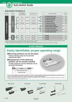
Best Pneumatics Auto Switch Guide Auto Switch Variations 2 Auto switch mounting style Electrical entry Auto switch model * These auto switches can be mounted with a band (except D-M9DVW and M9DAVL), a rail, a tie-rod or a square groove when auto switch mounting brackets are used. Refer to pages 1356, 1360, 1364, 1368 and 1369 for details. ** These auto switches can be mounted with a tie-rod when auto switch mounting brackets are used. Refer to page 1367 for details. Easily identifiable, proper operating range ►Mounting positions can be set easily. Proper operating range can be set while position...
Open the catalog to page 7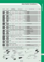
Auto Switch Variations 2 Auto switch mounting style Electrical entry Auto switch model The diagnostic output signal can be detected in an unsteady detecting area. I ^^^| - Band - Grommet |" | Water resistant (coolant) type Hygienic type With built-in OFF-delay timer (200 ms) Can be used in an environment where magnetic field disturbances are generated. Rail, Tie-rod, Direct \ Can be used in a high-temperature environment (Max. 150°C). Simple workpiece recognition is possible. * These auto switches can be mounted with a band (except D-M9DVW and M9DAVL), a rail, a tie-rod or a square groove when...
Open the catalog to page 8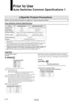
Auto Switches Common Specifications 1 _ASpecific Product Precautions Refer to the Auto Switch Precautions on pages 8 to 11 before using auto switches. Auto Switches Common Specifications * 1) Electrical entry: Connector type (A73C/A80C/C73C/C80C): 1000 VAC/min. (Between lead wire * 2) The terminal conduit type (D-A3/A3DA/A3DC/G39/G39A/G39C/K39/K39A/K39C), DIN terminal type (D-A44/A44A/A44C) and heat resistant auto switch (D-F7NJL) conform to IEC60529 Standard IP63. The trimmer type amplifier section (D-RDK) conforms to IP40. * 3) Excluding the solid state auto switches with a timer (D-M5DTL/G5NTL/F7NTL/F5NTL...
Open the catalog to page 9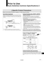
Auto Switches Common Specifications 2 ASpecific Product Precautions ^Refer to the Auto Switch Precautions on pages 8 to 11 before using auto switches. j Auto Switch Hysteresis Hysteresis is the distance between the position at which piston movement operates an auto switch to the position at which reverse movement turns the switch off. This hysteresis is included in part of the operating range Auto switch Hysteresis/Reed auto switch: 2 mm or less ^ ' V Solid state auto switch: 1 mm or less J Note) Hysteresis may fluctuate due to the operating environment. Please contact SMC if hysteresis causes...
Open the catalog to page 10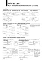
Auto Switches Connection and Example Basic Wiring Solid state 3-wire, NPN Solid state 3-wire, PNP 2-wire (Solid state) (Power supply for switch and load are separate) Example of Connection with PLC (Programmable Logic Controller) 'Sink input specifications Black inpuf •Source input specifications Black input • Connect according to the applicable PLC input specifications, as the connection method will vary depending on the PLC input specifications. Example of AND (Series) and OR (Parallel) Connection (Using relays) Brown - - ¿—[liad" When two auto switches because the load voltage will decline...
Open the catalog to page 11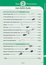
09.10.1 3:13 PM Page 1 2 Best Pneumatics Auto Switch Guide 2-2-46-UMASw-NakaT.qxd Auto Switch Guide Solid State Auto Switches General Purpose Type P.1277 Band, Rail, Tie-rod, Direct Mounting 2-Color Indication Type Band, Rail, Tie-rod, Direct Mounting 2-Color Indication Type with Diagnostic Output Water Resistant 2-Color Indication Type Hygienic Band, Rail, Tie-rod Mounting Band, Rail, Tie-rod, Direct Mounting Magnetic Field Resistant 2-Color Indication Type Heat Resistant 2-Color Indication Type Wide Range Detection Type Rail, Tie-rod, Direct Mounting Rail Mounting P.1306 General Purpose Type...
Open the catalog to page 12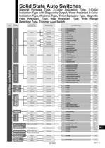
305-AutoSw-2.qxd 10.12.27 1:29 PM Page 1 Solid State Auto Switches General Purpose Type, 2-Color Indication Type, 2-Color Indication Type with Diagnostic Output, Water Resistant 2-Color Indication Type, Hygienic Type, Timer Equipped Type, Magnetic Field Resistant Type, Heat Resistant Type, Wide Range Detection Type, Trimmer Auto Switch Type Function Auto switch mounting style Electrical entry Page D-H7A1/H7A2/H7B 1278 D-G59/G5P/K59 1279 D-H7C 1280 D-G39/K39 1281 D-G39A/K39A 1282 D-F79/F7P/J79 1283 D-F7NV/F7PV/F7BV 1284 Connector D-J79C 1285 Grommet D-F59/F5P/J59/J51 1286 D-G39C/K39C 1287 Grommet...
Open the catalog to page 14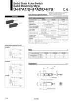
Solid State Auto Switch Band Mounting Style Auto Switch Internal Circuit Auto Switch Specifications Refer to SMC website for the details of international standards. PLC: Programmable Logic Controller • Lead wires — Oilproof heavy-duty vinyl cord, 03.4, 0.2 mm2, 3 cores (Brown, Black, Blue), 2 cores Note 1) Refer to page 1272 for solid state auto switch common specifications. Note 2) Refer to page 1272 for lead wire lengths. Indicator light Most sensitive position
Open the catalog to page 15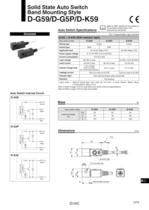
Solid State Auto Switch Band Mounting Style Auto Switch Internal Circuit Auto Switch Specifications Refer to SMC website for the details of international standards. PLC: Programmable Logic Controller • Lead wires — Oilproof heavy-duty vinyl cord, 04, 0.3 mm2, 3 cores (Brown, Black, Blue), 2 cores (Brown, Blue), 0.5 m Note 1) Refer to page 1272 for solid state auto switch common specifications. Note 2) Refer to page 1272 for lead wire lengths. \ Indicator light Most sensitive position
Open the catalog to page 16All SMC PNEUMATIC catalogs and technical brochures
 Vacuum Unit 2024
99 Pages
 Air Cylinder CJ2 Series
117 Pages
 AS-FS Series
36 Pages
 IDF series
12 Pages
 MHL2 Series
24 Pages
 JCM Serie
18 Pages
 EX245 Series
12 Pages
 Pin Cylinder CJP2/CDJP2/CJP
19 Pages
 5 Port Solenoid Valve VQC
63 Pages
 5 Port Solenoid Valve VQ
79 Pages
 SY
SY268 Pages
 5-p0979-0980-hep500
2 Pages
 5-p0977-0978-aep100
2 Pages
 5-p0966-0971-lmu
5 Pages
 5-p0960-0966-alb900
6 Pages
 5-p0956-0960-ald600
5 Pages
 5-p0948-0950-al800
3 Pages
 es70-44c-vx2
52 Pages
 es50-37-kq2
124 Pages
 ex-pcw
23 Pages
 1-p2124-2152-ex510
29 Pages
 1-p2111-2122-ex500
12 Pages
 1-p2063-2073-ex260
11 Pages
 4-p0147-0178-msu-mds
32 Pages
 es20-230b-crb2
59 Pages
 1-p1869-1878-vp3145
10 Pages
 VP300/500/700 series
42 Pages
 1-p1789-1829-vqz100
41 Pages
 1-p1727-1788-syj300
62 Pages
 5 Port Solenoid Valve S0700
111 Pages
 5 Port Solenoid Valve VF
59 Pages
 5 Port Solenoid Valve SV
127 Pages
 VH
VH9 Pages
 CUJ
CUJ41 Pages
 AL
AL3 Pages
 kj mm
kj mm9 Pages
 AQ
AQ4 Pages
 SY3000/5000-X13
2 Pages
 Series MB
24 Pages
 Series LES
23 Pages
 Series LEFB
16 Pages
 Series PF3W
28 Pages
 Series IDG?A/IDG
56 Pages
 Floating Joint
7 Pages
 Series IZS40/41/42
32 Pages
 Series LEY
7 Pages
 Series VHS
12 Pages
 Series CY1S
28 Pages
 SeriesCQ2/CQS/CQ
4 Pages
 In-line Air Filter
12 Pages
 5 Port Solenoid Valve
60 Pages
 Series CQ2/CQS
2 Pages
 AS series
2 Pages
 corporate guide
13 Pages
 ZP
ZP69 Pages
 ZFA
ZFA14 Pages
 ZA
ZA13 Pages
 MHF
MHF32 Pages
 MHZ
MHZ68 Pages
 CRB
CRB44 Pages
 RB
RB23 Pages
 CEP
CEP44 Pages
 RSK
RSK30 Pages
 CLK
CLK51 Pages
 MK
MK20 Pages
 GLJ
GLJ65 Pages
 MGJ
MGJ7 Pages
 Mx
Mx36 Pages
 MXH
MXH18 Pages
 My3
My356 Pages
 my1b
my1b20 Pages
 CC
CC15 Pages
 J
J14 Pages
 CQ2
CQ251 Pages
 standard cylinder
84 Pages
 VFN
VFN6 Pages
 SY3000
246 Pages
 SJ3A6
SJ3A618 Pages
 1301/IW
14 Pages
 CHQ/CHDQ
19 Pages
 AC
AC95 Pages
 HAW
HAW4 Pages
 HAA
HAA3 Pages
 ZB
ZB24 Pages
 CRB2
CRB235 Pages


Archived catalogs
 CJ1
CJ15 Pages
 SYJ
SYJ62 Pages
 SJ
SJ78 Pages
 Vacuum Unit ZK2 Series
60 Pages
 SYJ300/500/700 Series
62 Pages
