CRB2
1 /35Pages

CRB2
1 /35Pages
Catalog excerpts

Rotary Actuator/Vane Style îasic style With angle adjuster Double shaft Rubber bumper Basic type With auto switch With angle adjuster With auto switch and angle adjuster With flange
Open the catalog to page 1
The use of specially designed seals and stoppers now enables our compact vane type rotary actuators to ro- (Single vane type) Direct mounting The body of rotary actuator can be mounted directly. • Not possible to use direct mount type with units sized 10 to 40. Excellent reliability and durability Bearings are used in all series to support thrust and ra- dial loads. The use of a rubber bumper (except size 10) further improves reliability. different connecting locations (side and axial) The port location can be selected according to the ap- plication. (Types with various units sized 10 to 40 are...
Open the catalog to page 2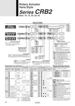
Rotary Actuator Vane Style auto switch With auto switch With auto switch With auto switch • (With auto switch unit and built-in magnet) * Refer to page 141 when the auto switch unit Is needed separately. Mounting style _Shaft type Double shaft with single flat (Size 10 to 30) Long shaft key, Short shaft with single flat (Size 40) (Connecting port location Rotating angle Vane type Auto switch Nil I Without auto switch (built-in magnet) | For the applicable auto switch model, refer * For details, refer to pages 69 to 80. Applicable Auto Switches/Refer to pages 761 to 809 for further information...
Open the catalog to page 3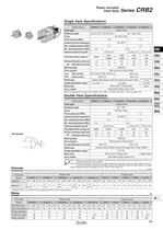
Rotary Actuator Vane Style Single Vane Specifications Note 3) Adjustment range in the table is for 270° Double Vane Specifications Note 1) Make sure to operate within the speed regulation range. Exceeding the maximum speed (0.3 sec/90°) can Jj cause the unit to stick or not operate. Note 2) The upper numbers in this section in the table indicate the energy factor when the rubber bumper is used (at the end of the rotation), and the lower numbers indicate the energy factor when the rubber bumper is not used. Note 3) Adjustment range in the table is for 100°. For 90°, refer to page 142. * Values...
Open the catalog to page 4
Rotary Actuator: Replaceable Shaft A shaft can be replaced with a different shaft type except for standard shaft type (W) Without auto switch Size — Rotating angle Vane type Port location — Made to order For details, refer to pages 74 to 80. Single flat / 0. i fi . A parallel key is used instead bingletlatof single flat for size 40. 0. i A parallel key Is used Instead bingletlat 0( single flat for size 40. Single flat Note ) Dimensions and tolerance of the shaft and single flat (a parallel key for size 40) are the same as the standard. With auto switch With angle adjusted With auto switch Shaft...
Open the catalog to page 5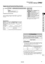
Rotary Actuator . f+DBn Vane Style Senes UMOZ Copper-free and Fluorine-free Rotary Actuator 20-CRB2BW P Size — Rotating angle Vane type Port location Use the standard vane type rotary actuators in all series to prevent any adverse effects to CRTs due to copper ions or The above may not be selected when the product comes with an auto switch or angle adjustment unit. Refer to pages 69, 70 and 79 for details. Be sure to read before handling. Refer to front matters 38 and 39 for Safety Instructions and pages 4 to 13 for Rotary Actuator and Auto Switch Precautions. Angle Adjuster 1. Since the maximum...
Open the catalog to page 6
Option Specifications: Flange (Size: 10,15, 20, 30) Note 1 ) The flange (with countersunk head screws) is not mounted on the actuator at the time Note 2) The flange can be mounted on the rotary actuator at 60-degree intervals. 6 X countersunk head screw for M3 conical seat and through-hole 6 X countersunk head screw for M3 conical seat and through-hole Rotary actuator 6 X countersunk head screw for M4 conical seat and through-hole 6 X countersunk head screw for M5 conical seat and through-hole
Open the catalog to page 7
P0045-P0114-E.qxd 08.9.29 1:22 PM Page 53 Rotary Actuator Vane Style Effective Output Direct Mounting of Body CRB2BW10 CRB2BW15 Screw 0.2 l ng Si 0.1 ne a ev e va ne 0.8 0.6 Do ub l 0.3 Effective torque (N·m) va ne 1.0 Do ub le 0.4 ne va le g Sin 0.2 CRB2 CRBU2 0 0 0 0.1 0.2 0.3 0.4 0.5 0.6 0.7 0 0.1 0.2 0.3 0.4 0.5 0.6 0.7 Operating pressure (MPa) Operating pressure (MPa) CRB2BW30 CRB2BW40 8 0.8 ne le ng Si va 0.4 0 ne le va ing 2 S 0 0.1 0.2 0.3 0.4 0.5 0.6 0.7 Operating pressure (MPa) va g in S 0 0 0.2 0.4 0.6 0.8 1.0 0 Operating pressure (MPa) 0.2 0.4 0.6 0.8 1.0 Operating pressure (MPa)...
Open the catalog to page 8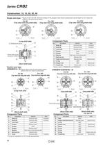
SinglG VanG type * Figures for 90° and 180° show the condition of the actuators when B port is pressurized, and the figure for 270° shows the position of the ports during rotation. (Top view from long shaft side) (Top view from long shaft side) (Top view from long shaft side) (Long shaft side) Component Parts Internal rubber bumper, (Short shaft side) Double vane type CRB2BW10-DD/Figures below show the intermediate rotation position when A or B port is pressurized. (Top view from long shaft side) (Top view from long shaft side) (Top view from long shaft side) (Top view from long shaft side) (Long...
Open the catalog to page 9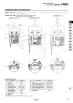
Construction (With auto switch unit) Rotary Actuator . f+DBn Vane Style Series UMOZ Single Vane type • Following figures show actuators for 90° and 180° when B port is pressurized. Double Vane type • Following figures show the intermediate rotation position when A or B port is pressurized. (Same switch units are used for both single and double vane types.) Hexagon socket head set screw Round head Phillips screw Round head Phillips screw Round head Phillips screw Round head Phillips screw Stainless steel Stainless steel Stainless steel Stainless steel Stainless steel Stainless steel * For CDRB2BW10,...
Open the catalog to page 10
SinglG VanG typs • Following figures show actuators for 90° and 180° when B port is pressurized. <Port location: Side ported> <Port location: Side ported> <Port location: Axial ported> Note) Depths of Q1 and Q2 with the + mark indicate that the holes go through both bodies (A) and (B). Note) The pre-drilled mounting threads for CRB2BW15, 20, and 30, 3 mounting holes depicted with the-k marks are for tightening the actuator and not to be used for external mounting. ^mmj
Open the catalog to page 11All SMC PNEUMATIC catalogs and technical brochures
 Vacuum Unit 2024
99 Pages
 Air Cylinder CJ2 Series
117 Pages
 AS-FS Series
36 Pages
 IDF series
12 Pages
 MHL2 Series
24 Pages
 JCM Serie
18 Pages
 EX245 Series
12 Pages
 Pin Cylinder CJP2/CDJP2/CJP
19 Pages
 5 Port Solenoid Valve VQC
63 Pages
 5 Port Solenoid Valve VQ
79 Pages
 SY
SY268 Pages
 5-p0979-0980-hep500
2 Pages
 5-p0977-0978-aep100
2 Pages
 5-p0966-0971-lmu
5 Pages
 5-p0960-0966-alb900
6 Pages
 5-p0956-0960-ald600
5 Pages
 5-p0948-0950-al800
3 Pages
 es70-44c-vx2
52 Pages
 es50-37-kq2
124 Pages
 ex-pcw
23 Pages
 1-p2124-2152-ex510
29 Pages
 1-p2111-2122-ex500
12 Pages
 1-p2063-2073-ex260
11 Pages
 4-p0147-0178-msu-mds
32 Pages
 es20-230b-crb2
59 Pages
 1-p1869-1878-vp3145
10 Pages
 VP300/500/700 series
42 Pages
 1-p1789-1829-vqz100
41 Pages
 1-p1727-1788-syj300
62 Pages
 5 Port Solenoid Valve S0700
111 Pages
 5 Port Solenoid Valve VF
59 Pages
 5 Port Solenoid Valve SV
127 Pages
 VH
VH9 Pages
 CUJ
CUJ41 Pages
 AL
AL3 Pages
 kj mm
kj mm9 Pages
 AQ
AQ4 Pages
 SY3000/5000-X13
2 Pages
 Series MB
24 Pages
 Series LES
23 Pages
 Series LEFB
16 Pages
 Series PF3W
28 Pages
 Series IDG?A/IDG
56 Pages
 Floating Joint
7 Pages
 Series IZS40/41/42
32 Pages
 Series LEY
7 Pages
 Series VHS
12 Pages
 Series CY1S
28 Pages
 SeriesCQ2/CQS/CQ
4 Pages
 In-line Air Filter
12 Pages
 5 Port Solenoid Valve
60 Pages
 Series CQ2/CQS
2 Pages
 AS series
2 Pages
 corporate guide
13 Pages
 ZP
ZP69 Pages
 ZFA
ZFA14 Pages
 ZA
ZA13 Pages
 MHF
MHF32 Pages
 MHZ
MHZ68 Pages
 CRB
CRB44 Pages
 D
D117 Pages
 RB
RB23 Pages
 CEP
CEP44 Pages
 RSK
RSK30 Pages
 CLK
CLK51 Pages
 MK
MK20 Pages
 GLJ
GLJ65 Pages
 MGJ
MGJ7 Pages
 Mx
Mx36 Pages
 MXH
MXH18 Pages
 My3
My356 Pages
 my1b
my1b20 Pages
 CC
CC15 Pages
 J
J14 Pages
 CQ2
CQ251 Pages
 standard cylinder
84 Pages
 VFN
VFN6 Pages
 SY3000
246 Pages
 SJ3A6
SJ3A618 Pages
 1301/IW
14 Pages
 CHQ/CHDQ
19 Pages
 AC
AC95 Pages
 HAW
HAW4 Pages
 HAA
HAA3 Pages
 ZB
ZB24 Pages


Archived catalogs
 CJ1
CJ15 Pages
 SYJ
SYJ62 Pages
 SJ
SJ78 Pages
 Vacuum Unit ZK2 Series
60 Pages
 SYJ300/500/700 Series
62 Pages
