CRB
1 /44Pages

CRB
1 /44Pages
Catalog excerpts

Rotary Actuator Many combinations available! With auto switch unit Double shaft Double shaft (W shaft) O Port locations modified Change in angle: Parallel piping (0°), Conventional type (25° (New Parallel piping Conventional type The port size is unified to M3. * Side ported (Size 10,15) With angle adjuster unit With auto switch unit The use of specially designed seals compact vane type rotary actuators to rotate up to 270°. (Single vane type) Rotating angle 11 Rotating angle adjustment range
Open the catalog to page 1
Series CRB2 Screw x 3 Direct mounting The rotary actuator body can be mounted directly. Not possible for size 10 to 40 with unit(s). CRB2 The mounting position of the auto switch can be set freely. The switch can be fixed in the desired position in the circumferential direction. Connecting port location: Side ported or Axial ported The port location can be selected according to the application. Side ported (Size 10 to 40 with unit(s) are side ported only.) Axial ported Double vane type is standardized for 90 and 100 . The outside dimensions of the double vane type are equivalent to those of the...
Open the catalog to page 2
Working Principle/How to Mount Loads series CRB2 Vane Type 1. It consists of a shaft that is integrated with the vane that slides along the inner surface of the body, and a stopper. 2. The air that is supplied from port A pushes the vane, thus creating torque in the shaft. 3. The air in the exhaust chamber discharges via port B and rotates clockwise. 4. The vane stops as it comes in contact with the stopper. 5. Similarly, when air is supplied from port B, it rotates It consists of a shaft that is integrated with the 2 vanes that slide along the inner surface and 2 stoppers. The air that is supplied...
Open the catalog to page 3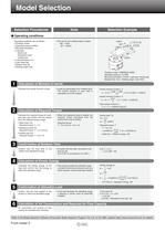
Model Selection Selection Procedures Selection Example Operating conditions are as follows: • Tentative model • Mounting orientation • Load type Static load Resistance load Inertial load • The unit for the rotating angle is radian. "| I Calculation of Moment of Inertia Calculate the Inertial moment of load. • Loads are generated from multiple parts. The inertial moment of each load is calculated, and then totaled. 2 I Calculation of Required Torque Calculate the required torque for each load type and confirm that the values fall In the effective torque range. • When the resistance load is rotated,...
Open the catalog to page 4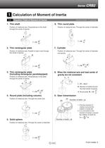
Q Calculation of Moment of Inertia 1-1 Equation Table of Moment of Inertia Position of rotational axis: Perpendicular to the shaft through the center of gravity 2. Thin rectangular plate Position of rotational axis: Parallel to side b and through 3. Thin rectangular plate (Including rectangular parallelepiped) Position of rotational axis: Perpendicular to the plate through the center of gravity 4. Round plate (Including column) Position of rotational axis: Through the center axis I: Moment of inertia m: Load mass 6. Thin round plate Position of rotational axis: Through the center of diameter...
Open the catalog to page 5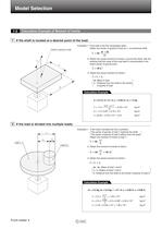
Model Selection 1-2 Calculation Example of Moment of Inertia 1 If the shaft is located at a desired point of the load: Center of gravity of load Example) 1. If the load is the thin rectangular plate: Obtain the center of gravity of load as li, a provisional shaft. 2. Obtain the actual moment of inertia I2 around the shaft, with the premise that the mass of the load itself is concentrated in the load's center of gravity point. 3. Obtain the actual moment of inertia I. L : Distance from the shaft to the center Calculation Example 2 If the load is divided into multiple loads: Example) 1. If the...
Open the catalog to page 6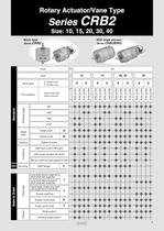
Rotary Actuator/Vane Type Basic type Vane type Port location With angle adjuster
Open the catalog to page 7
Rotary Actuator Vane Type auto switch With auto switch With auto switch With auto switch (With auto switch unit and built-in magnet) * Refer to page 33 when the auto switch unit is needed separately. Shaft type* 1 Connecting port locati on Patterned sequencing order* For details, refer to pages 19 to 30. Rotating angle Vane type Auto switch Without auto switch (Built-in magnet) * Single shaft with single flat (size 10 to 30); Key (size 40) ** Double shaft with single flat (Size 10 to 30) Long shaft key, Short shaft with single flat (Size 40) Refer to Page 4 for details of simple specials J, K,...
Open the catalog to page 8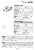
Rotary Actuator Vane Type Single Vane Specifications Note 2) The upper numbers in this section in the table indicate the energy factor when the rubber bumper is used (at the end of the rotation), and the lower numbers indicate the energy factor when the rubber bumper is not used. Note 3) Adjustment range in the table is for 270°. For 90° and 180°, refer to page 15. Double Vane Specifications Note 1) Make sure to operate within the speed regulation range. Exceeding the maximum speed (0.3 sec/90°) can cause the unit to stick or not operate. Note 3) Adjustment range in the table is for 100°. For...
Open the catalog to page 9
Rotary Actuator: Replaceable Shaft A shaft can be replaced with a different shaft type, except for standard shaft type Without auto switch P Size — Rotating angle Patterned sequencing order Vane type Port location Z — Made to Order For details, refer to pages 24 to 30. Round shaft Single tlat/ Round shaft Round shaft A parallel key Is used Instead of single flat for size 40. Single flat Single flat/*! Note) Dimensions and tolerance of the shaft and single flat (a parallel key for size 40) are the same as the standard. With auto switch With angle adjuster unit With auto switch Size — Rotating...
Open the catalog to page 10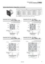
Vane Type SeneS \*r\D¿ Optional Specifications: Flange (Size: 10,15, 20, 30) Note 1 ) The flange (with countersunk head screws) is not mounted on the actuator at the time Note 2) The flange can be mounted on the rotary actuator at 60° intervals. 6 X countersunk head screw for M3 conical seat and through-hole 6 X countersunk head screw for M3 conical seat and through-hole Rotary actuator 6 X countersunk head screw for M4 conical seat and through-hole 6 X countersunk head screw for M5 conical seat and through-hole
Open the catalog to page 11All SMC PNEUMATIC catalogs and technical brochures
 Vacuum Unit 2024
99 Pages
 Air Cylinder CJ2 Series
117 Pages
 AS-FS Series
36 Pages
 IDF series
12 Pages
 MHL2 Series
24 Pages
 JCM Serie
18 Pages
 EX245 Series
12 Pages
 Pin Cylinder CJP2/CDJP2/CJP
19 Pages
 5 Port Solenoid Valve VQC
63 Pages
 5 Port Solenoid Valve VQ
79 Pages
 SY
SY268 Pages
 5-p0979-0980-hep500
2 Pages
 5-p0977-0978-aep100
2 Pages
 5-p0966-0971-lmu
5 Pages
 5-p0960-0966-alb900
6 Pages
 5-p0956-0960-ald600
5 Pages
 5-p0948-0950-al800
3 Pages
 es70-44c-vx2
52 Pages
 es50-37-kq2
124 Pages
 ex-pcw
23 Pages
 1-p2124-2152-ex510
29 Pages
 1-p2111-2122-ex500
12 Pages
 1-p2063-2073-ex260
11 Pages
 4-p0147-0178-msu-mds
32 Pages
 es20-230b-crb2
59 Pages
 1-p1869-1878-vp3145
10 Pages
 VP300/500/700 series
42 Pages
 1-p1789-1829-vqz100
41 Pages
 1-p1727-1788-syj300
62 Pages
 5 Port Solenoid Valve S0700
111 Pages
 5 Port Solenoid Valve VF
59 Pages
 5 Port Solenoid Valve SV
127 Pages
 VH
VH9 Pages
 CUJ
CUJ41 Pages
 AL
AL3 Pages
 kj mm
kj mm9 Pages
 AQ
AQ4 Pages
 SY3000/5000-X13
2 Pages
 Series MB
24 Pages
 Series LES
23 Pages
 Series LEFB
16 Pages
 Series PF3W
28 Pages
 Series IDG?A/IDG
56 Pages
 Floating Joint
7 Pages
 Series IZS40/41/42
32 Pages
 Series LEY
7 Pages
 Series VHS
12 Pages
 Series CY1S
28 Pages
 SeriesCQ2/CQS/CQ
4 Pages
 In-line Air Filter
12 Pages
 5 Port Solenoid Valve
60 Pages
 Series CQ2/CQS
2 Pages
 AS series
2 Pages
 corporate guide
13 Pages
 ZP
ZP69 Pages
 ZFA
ZFA14 Pages
 ZA
ZA13 Pages
 MHF
MHF32 Pages
 MHZ
MHZ68 Pages
 D
D117 Pages
 RB
RB23 Pages
 CEP
CEP44 Pages
 RSK
RSK30 Pages
 CLK
CLK51 Pages
 MK
MK20 Pages
 GLJ
GLJ65 Pages
 MGJ
MGJ7 Pages
 Mx
Mx36 Pages
 MXH
MXH18 Pages
 My3
My356 Pages
 my1b
my1b20 Pages
 CC
CC15 Pages
 J
J14 Pages
 CQ2
CQ251 Pages
 standard cylinder
84 Pages
 VFN
VFN6 Pages
 SY3000
246 Pages
 SJ3A6
SJ3A618 Pages
 1301/IW
14 Pages
 CHQ/CHDQ
19 Pages
 AC
AC95 Pages
 HAW
HAW4 Pages
 HAA
HAA3 Pages
 ZB
ZB24 Pages
 CRB2
CRB235 Pages


Archived catalogs
 CJ1
CJ15 Pages
 SYJ
SYJ62 Pages
 SJ
SJ78 Pages
 Vacuum Unit ZK2 Series
60 Pages
 SYJ300/500/700 Series
62 Pages
