

CEP

CEP
- Resolution: 0.01 mm with an accuracy of ±0.02 mm.
- Output Function: RS-232C BCD with 5 points output and bank switching for 20 points, and 31 points for binary output.
- Power Supply: 12 to 24 VDC.
- Seal Material: Two types available, made to order.
- Mounting: Auto switch mounting orientation can be freely selected on three surfaces.
- High Precision Stroke Reading Cylinder (CEP1) and Stroke Reading Cylinder (CE1) are available with a special scraper as standard for environments exposed to fluids.
- Measurement is possible throughout the full stroke range, with the home position reset by pressing the cylinder rod to the reference plane.
- Ensure the load is applied in the axial direction to avoid rotational torque on the piston rod.
- Protect the cylinder from contact with liquids and avoid environments with strong magnetic fields.
- Noise countermeasures include connecting the shield wire to FG and using separate power sources from large motors.
- Detection of die assembly’s deceleration point, length/breadth discrimination, inspection of machined holes, and measurement of machining dimensions.
- Can confirm the press-in of a hydraulic cylinder by detecting its stroke and maintain a constant height of measuring workpiece height.
- The stroke reading cylinder uses an MR element to detect rod movement, outputting the piston stroke movement as a pulse signal.
- High precision models amplify and divide signals to achieve a resolution of 0.01 mm.
- Ensure proper mounting to avoid rotational torque and protect the sensor unit from liquids.
- Implement noise suppression techniques when operating near noise-generating equipment.
- Various mounting styles, bore sizes, and sensor cable lengths are available.
- Auto switch options include different wiring and load voltage configurations.
The document outlines the specifications for various models of the CEU series multi-counter, including CEU5, CEU5-D, CEU5P, CEU5P-D, CEU5B, CEU5B-D, CEU5PB, and CEU5PB-D. These models are designed for surface mounting and feature an adding-subtracting type operating system with modes for operation, data setting, and function setting. They include an external reset terminal and an LCD display with backlight, capable of displaying 6 digits. The memory holds setting values and count values, with a warning display after approximately 800,000 writes.
Procedures:
The document provides detailed instructions on wiring and connecting the multi-counter to external equipment. It specifies the power source requirements, control signal input methods, and output circuit configurations. The document emphasizes the importance of adhering to the maximum voltage and amperage ratings to prevent damage to the electric circuit.
Standards and Norms:
The CEU series counters comply with CE standards when connected to specific stroke reading cylinders. The document specifies the environmental conditions for operation, including ambient temperature and humidity, noise resistance, shock resistance, and impact resistance.
Recommendations:
For improved anti-noise performance, the document recommends using a varistor, noise filter, or ferritic core. It also advises on the correct wiring combinations to ensure proper counting direction and functionality.
Key Data from Tables and Diagrams:
The document includes tables detailing the specifications for each model, such as power supply voltage, power consumption, withstand voltage, insulation resistance, and mass. Diagrams illustrate the connection methods and output configurations, providing visual guidance for installation and operation.
Critical Information:
Key parameters include the maximum counting speed of 100 kHz, the maximum output rating of 30 VDC and 50 mA, and the requirement for a power source with 90 to 264 VAC or 21.6 to 26.4 VDC. The document also highlights the importance of using the correct input signal types and maintaining the specified environmental conditions for optimal performance.
- Prescale Setting: Adjusted by pressing the SEL key while PRESCL is flashing. Users can select between CEP1, CE1, or manual modes using UP/DOWN keys.
- Multiplication Function: Options include x1, x2, or x4, selected with UP/DOWN keys. The SEL key shifts to the next item.
- Prescale Value: Users can set the number to be added for each count, adjusting digits with LEFT/RIGHT keys and values with UP/DOWN keys.
- Decimal Point Position: Shifted with LEFT/RIGHT keys and stored with the SET key.
- Output System: Selected by pressing the SEL key while OUTPUT is flashing. Options include normal or binary output.
- Input Type: Selected by pressing the SEL key while INPUT is flashing, with options for phase difference input or separate input.
- Count Value Backup: Enabled or disabled with UP/DOWN keys and stored with the SET key.
- RS-232C Communication Speed: Options range from 1200 to 19200, selected with UP/DOWN keys.
- Unit Number Registration: Numerical values set with direction keys, ranging from 00 to 99.
- MODE Key: Switches between count and setting modes.
- SHIFT Key: Shifts digits for data input.
- SEL Key: Shifts the flashing cursor without storing settings.
- SET Key: Registers settings after changes.
- Bank Switching: Allows for preset output without bank switching, using binary system output.
- BCD Output: Expresses decimal numbers with a 4-digit binary number.
- Display Offset Function: Allows setting of tolerances for preset values, enhancing performance in parts inspections.
- Hold Function: Retains the current count value in memory for later retrieval.
Catalog excerpts

Stroke Reading Cylinder and Counter > Output: 5 points (Bank switching: 20 points) 31 points (Binary output) High Precision Stroke Reading Cylinder Stroke Reading
Open the catalog to page 1
Measurement is possible throughout the full stroke range. Hp home position can be anywhere within the cylinder stroke. When the counter is reset by pressing the cylinder rod to the reference plane, that point becomes the home position. Can be used in an environment where the product is exposed to fluids (water, oil, coolant, etc.) Series CEP1 With special scraper as standard * The standard type of Series CE1 does not come with a scraper. Series CE1 Special order (with scraper) * Contact SMC since cylinders with a scraper are special orders. High Precision Stroke Reading Cylinder (CEP1) • Special...
Open the catalog to page 2
Application Examples Parts inspection parts, discriminates between good and defective articles, hydraulic cylinder by detecting its Even if the size of the workpiece changes, the point of press-in completion can be easily changed. deceleration point Since the deceleration point of the die easily changed after replacement of Length/breadth discrimination Distinguishes either lengthwise or crosswise while correcting the Maintains a constant height of I measuring workpiece height. ! Detection of lifter position lifter's stroke. I Inspection of machined holes Can detect machined hole depth, burrs...
Open the catalog to page 3
Stroke Reading Cylinder Series Measurement Principle The amount of rod movement in the stroke reading cylinder is detected using an MR element (magnetic resistance element) whose resistance value changes due to magnetic force. The detection unit containing this MR element is called the sensor head. An amplifying circuit and a dividing circuit are required to produce output which can be read by the counter, and these are attached to the cylinder case. The sensor head and amplifier section together are referred to as the sensor unit. Sensor head Cylinder unit The stroke reading cylinder is equipped...
Open the catalog to page 4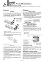
Specific Product Precautions Be sure to read before handling. Refer to front matters 42 and 43 for Safety Instructions and pages 3 to 11 for Actuator and Auto Switch Precautions. 1. When screwing a nut or fitting, etc. onto the threaded section at the end of the piston rod, return the piston rod to its fully retracted position, and grasp the exposed portion of the rod across two parallel sides with a wrench. In the case of the high precision stroke reading cylinder, there are no parallel sides. Secure the workpiece with a double nut. Note) Do not apply rotational torque to the piston rod. 2....
Open the catalog to page 5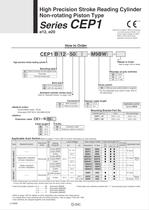
High Precision Stroke Reading Cylinder Non-rotating Piston Type Note) CE compliant: When connecting power supply voltage 24 VDC) operation manual for details. High precision stroke reading cylinder Mounting style Bore size Standard cylinder stroke (mm) Refer to "Standard Stroke" on page 1445. Referto page 1445 for details. Number of auto switches Auto switch Nil I Without auto switch (Built-in magnet) For the applicable auto switch model, refer to Sensor cable length Applicable counter Mounting Bracket Part No. Cable length Applicable AutO Switch/Refer to pages 1719 to I827 for further information...
Open the catalog to page 7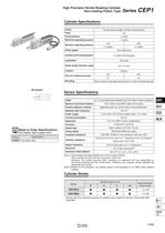
High Precision Stroke Reading Cylinder Non-rotating Piston Type SOflOS Cylinder Specifications Made to Order Specifications (For details, refer to page 1918.) Fluororubber seals Sensor Specifications Note 1) This includes the digital display error of the counter (CEU5). When strokes are over 100 mm, accuracy is ±0.05 mm. Moreover, the overall accuracy after mounting on equipment will vary depending on mounting conditions and the environment. Therefore, the customer should calibrate the Note 2) Except for the connector, the cylinder section is the equivalent of an SMC water resistant Cylinder...
Open the catalog to page 8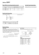
Mass (Without mounting bracket/connector)_ Auto Switch Proper Mounting Position Regarding dimensions for the auto switch proper mounting position (at stroke end), refer to page 1452. Electrical Wiring Output type The output signal of the high precision stroke reading cylinder is A/B phase difference output (open collector output) as shown in the figure below. The relation between the movement distance and the signal output of the high precision stroke reading cylinder is that for each 0.04 mm of movement a one pulse signal is output to both output terminals A and B. In order to measure with a...
Open the catalog to page 9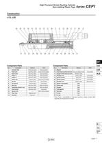
High Precision Stroke Reading Cylinder Non-rotating Piston Type Series Component Parts Component Parts * Since there is a possibility of improper operation, please contact SMC regarding the replacement of seals.
Open the catalog to page 10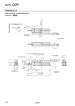
Direct mounting, rod side tapped style: Metal connector Width across flats 8 4 X M5 X 0.8 depth 6 (Bottom 04.3 through-hole)
Open the catalog to page 11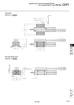
High Precision Stroke Reading Cylinder Non-rotating Piston Type Series Foot style: Rod side flange style:
Open the catalog to page 12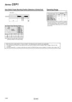
Auto Switch Proper Mounting Position (Detection at Stroke End) Operating Range Auto switch Note) Adjust the auto switch after confirming the operating conditions in the actual setting. ► Since the operating range is provided as a guideline including hysteresis, it cannot be guaranteed (assuming approximately ±30% dispersion). It may vary substantially depending on an ambient Other than the models listed in "How to Order", the following auto switches are applicable. * For solid state auto switches, auto switches with a pre-wired connector are also available. Referto pages 1784 and 1785 * Normally...
Open the catalog to page 15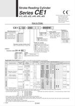
Stroke Reading Cylinder Note) CE compliant: When connecting Refer to the counter operation Mounting style* Bore size Cable length •Auto switch auto switches Without auto switch (Built-in magnet) switch model, refer to Standard cylinder stroke (mm) Refer to "Standard Stroke" on page 1455 (Applicable bore size 040 to 063) Applicable counter Cable length * 012, 020, 032: Without cushion only. Applicable AutO Switch/Refer to pages 1719 to I827 for further information on auto switches. ** Water resistant type auto switches can be mounted on the above models, but in such case SMC cannot guarantee water...
Open the catalog to page 17All SMC PNEUMATIC catalogs and technical brochures
 Vacuum Unit 2024
99 Pages
 Air Cylinder CJ2 Series
117 Pages
 AS-FS Series
36 Pages
 IDF series
12 Pages
 MHL2 Series
24 Pages
 JCM Serie
18 Pages
 EX245 Series
12 Pages
 Pin Cylinder CJP2/CDJP2/CJP
19 Pages
 5 Port Solenoid Valve VQC
63 Pages
 5 Port Solenoid Valve VQ
79 Pages
 SY
SY268 Pages
 5-p0979-0980-hep500
2 Pages
 5-p0977-0978-aep100
2 Pages
 5-p0966-0971-lmu
5 Pages
 5-p0960-0966-alb900
6 Pages
 5-p0956-0960-ald600
5 Pages
 5-p0948-0950-al800
3 Pages
 es70-44c-vx2
52 Pages
 es50-37-kq2
124 Pages
 ex-pcw
23 Pages
 1-p2124-2152-ex510
29 Pages
 1-p2111-2122-ex500
12 Pages
 1-p2063-2073-ex260
11 Pages
 4-p0147-0178-msu-mds
32 Pages
 es20-230b-crb2
59 Pages
 1-p1869-1878-vp3145
10 Pages
 VP300/500/700 series
42 Pages
 1-p1789-1829-vqz100
41 Pages
 1-p1727-1788-syj300
62 Pages
 5 Port Solenoid Valve S0700
111 Pages
 5 Port Solenoid Valve VF
59 Pages
 5 Port Solenoid Valve SV
127 Pages
 VH
VH9 Pages
 CUJ
CUJ41 Pages
 AL
AL3 Pages
 kj mm
kj mm9 Pages
 AQ
AQ4 Pages
 SY3000/5000-X13
2 Pages
 Series MB
24 Pages
 Series LES
23 Pages
 Series LEFB
16 Pages
 Series PF3W
28 Pages
 Series IDG?A/IDG
56 Pages
 Floating Joint
7 Pages
 Series IZS40/41/42
32 Pages
 Series LEY
7 Pages
 Series VHS
12 Pages
 Series CY1S
28 Pages
 SeriesCQ2/CQS/CQ
4 Pages
 In-line Air Filter
12 Pages
 5 Port Solenoid Valve
60 Pages
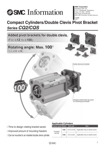 Series CQ2/CQS
2 Pages
 AS series
2 Pages
 corporate guide
13 Pages
 ZP
ZP69 Pages
 ZFA
ZFA14 Pages
 ZA
ZA13 Pages
 MHF
MHF32 Pages
 MHZ
MHZ68 Pages
 CRB
CRB44 Pages
 D
D117 Pages
 RB
RB23 Pages
 RSK
RSK30 Pages
 CLK
CLK51 Pages
 MK
MK20 Pages
 GLJ
GLJ65 Pages
 MGJ
MGJ7 Pages
 Mx
Mx36 Pages
 MXH
MXH18 Pages
 My3
My356 Pages
 my1b
my1b20 Pages
 CC
CC15 Pages
 J
J14 Pages
 CQ2
CQ251 Pages
 standard cylinder
84 Pages
 VFN
VFN6 Pages
 SY3000
246 Pages
 SJ3A6
SJ3A618 Pages
 1301/IW
14 Pages
 CHQ/CHDQ
19 Pages
 AC
AC95 Pages
 HAW
HAW4 Pages
 HAA
HAA3 Pages
 ZB
ZB24 Pages
 CRB2
CRB235 Pages


Archived catalogs
 CJ1
CJ15 Pages
 SYJ
SYJ62 Pages
 SJ
SJ78 Pages
 Vacuum Unit ZK2 Series
60 Pages
 SYJ300/500/700 Series
62 Pages
