

CC

CC
- Converter capacity and valve unit flow rate control offer a wide range of series.
- Operating pressure: 0.5 MPa, with no load and specific piping dimensions.
- Select the bore size of the air-hydro cylinder based on the theoretical output table, ensuring the output-to-load ratio is 0.5 or less.
- Choose a converter size that maintains an oil level speed of 200 mm/s or less.
- Select the required valve unit functions based on application needs.
- Determine the valve unit size using the maximum operating speed data.
- Stop Valve: Prevents load dropping in emergencies.
- Skip Valve: Allows fast forward to working process and multipoint intermediate stops.
- Flow Control Valve: Provides uniform driving for load fluctuations with pressure compensation.
- Throttle Valve/Speed Controller: Ensures smooth operation at low speeds or when starting.
- Ensure proper oil level maintenance to avoid leaks.
- Install an exhaust cleaner on the direction switching valve.
- For synchronized operation, use a mechanical device for regulating individual cylinders.
- Use a pneumatic speed controller for fast-forward speed control when necessary.
1. Air Pressure Requirements: The pilot pressure must be set to the operating pressure of the cylinder or higher, with pneumatic piping requiring 0.3 to 0.7 MPa of air pressure.
2. Valve Operation: Stop and skip valves should be normally closed. When using a solenoid valve, ensure proper pneumatic piping.
1. Speed Considerations: Restrictions in fittings or 90° bends may affect speed.
2. Cavitation Prevention: Configure piping with an ascending gradient, shorten hydraulic piping, and avoid vertical downward port positions.
1. Double-side Hydro: Leakage occurs with sliding movement, requiring maintenance of the converter’s oil level.
2. Single-side Hydro: Air may mix with oil, affecting cylinder speed and valve accuracy. Regular checks and air bleeding are necessary.
1. Converter Positioning: Different procedures are required depending on whether the converter is higher or lower than the cylinder.
2. Oil Type: Use petroleum-based turbine hydraulic oil with appropriate viscosity (40 to 100 mm²/s).
1. Series VNA/Process Valve: Suitable for compressed air and air-hydro circuit control, with variations available for different applications.
2. Operation Capacity: Can supplement conventional air-hydro valve units, suitable for large bore cylinders and multiple cylinder operations.
1. Supply Pressure: 0.49 MPa with ISO VG32 hydraulic fluid.
2. Piping Specifications: Various diameters and types are standardized for different applications.
Catalog excerpts
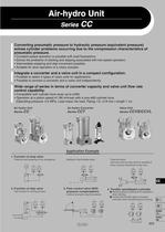
Converting pneumatic pressure to hydraulic pressure (equivalent pressure) solves cylinder problems occurring due to the compression characteristics of pneumatic pressure. • Constant-speed operation is possible with load fluctuations. • Solves the problems of sticking and slipping associated with low-speed operation. • Intermediate stopping and skip movement possible. • Suitable for slow operation of a rotary actuator. Integrate a converter and a valve unit in a compact configuration. • Possible to select 4 types of valve units for applications. • Possible to connect a converter and a valve unit independently. Wide range of series in terms of converter capacity and valve unit flow rate control capability. • Compatible with cylinder bore sizes up to 0300. • Operation at a piston speed of 180 mm/sec with a size 08O cylinder bore. (Operating pressure: 0.5 MPa, Load mass: No load, Piping: I.D. o19 mm x length 1 m) Air-hydro Unit Air-hydro Converter Valve Unit Series CCVS/CCVL Application Example 1. Function of stop valve Prevents load dropping (In an emergency) 2. Function of skip valve Fast forward to working process Multipoint intermediate stops 3. Flow control valve (With pressure compensation) Uniform driving for load fluctuations (Not only solid but also liquid is available if there is pump mechanism at the end.) 4. Throttle valve/Speed controller • Working without jumping at low speeds or when starting. • Control with throttle valve and speed controller when transferring and carrying.
Open the catalog to page 1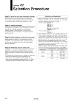
Selection Procedure Step (1) Select the bore size of air-hydro cylinder First of all, select a bore size from data (D) <Theoretical Output Table>. When making a selection, the ratio between the theoretical output and the load should be 0.5 or less. Step (2) Select converter_ Select the nominal diameter and the effective oil level stroke from data (A), <Cylinder Displacement and Converter Capacity Diagram>. When selecting a converter by its nominal diameter, the converter's oil level speed should be Step (3) Select required function for valve unit Select a model from data (B), <Converter and Valve...
Open the catalog to page 2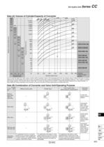
P0923-P0938-E.qxd 08.10.3 2:15 PM Page 925 Air-hydro Unit Series CC Data (A) Volume of Cylinder/Capacity of Converter 800 700 600 500 400 300 200 00 10,000 8,000 ø3 0 5 ø2 0 ø20 ø180 ø160 ø140 ø80 6,000 5,000 4,000 600 500 ø63 3,000 400 ø50 2,000 Effective oil level stroke (mm) 300 200 ø125 ø100 ø40 500 300 100 200 300 100 200 150 Capacity of converter (cm3) 400 1,000 800 ø30 ø25 CRA1H100-180 ø20 600 500 400 CRA1H100-90 300 CRA1H80-180 200 CRA1H80-90 CRA1H63-180 50 100 100 80 CRA1H63-90 CRA1H50-180 60 50 40 50 CRA1H50-90 30 160 100 63 20 40 100 200 300 400 500 600 700 800 Selected model of rotary...
Open the catalog to page 3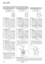
Data (C) Maximum Driving Speed of Valve Unit and Cylinder Cylinder driving speed when operating flow control valve Cylinder driving speed when operating throttle valve Cylinder driving speed when operating stop valve Condition: Operating press.: 0.3 to 0.7 MPa Load ratio: 50% or less Operating oil: Additive turbine oil Class 1 Piping bore Piping bore Piping bore ^Caution on Circuit Construction I.The converter's oil level must be properly maintained because a slight oil leak from the sliding of the seal of the air-hydro 2. Make sure to install an exhaust cleaner (Series AMC/Best Pneumatics No....
Open the catalog to page 4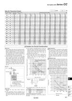
Air-hydro Unit Series CC Data (D) Theoretical Output A Caution on Circuit Construction Skip valve 1. When using a skip valve, the maximum allow- able ratio between the high speed and the low speed is approximately 3:1. If this ratio is too large, air bubbles could form due to cavitations, and could lead to the conditions described in Product Specific Precautions (page 936). 2. If the skip valve of an air-hydro unit with skip valve is operated, because it is not equipped with a speed control valve, the fast-forward speed will be determined by the model, piping conditions, and the actuator used....
Open the catalog to page 5
Air-hydro Unit The air-hydro unit consists of a converter and a valve unit that are compactly integrated. It converts air pressure to an equivalent hydraulic pressure, and this hydraulic pressure is used for operating an actuator, thus solving the problem that is associated with the compression characteristics of air. Thus, in spite of using pneumatic equipment, it performs similarly to a hydraulic unit, operating at a constant speed during starting or in the presence of load fluctuations, and at the same time solving the problems of sticking and slipping associated with low speed operations....
Open the catalog to page 6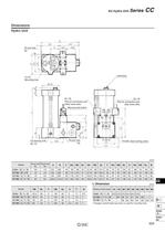
Air-hydro Unit Series CC Hydro Unit ■ Hexagon socket head cap screw is used for mounting hole.
Open the catalog to page 7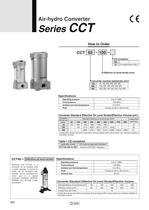
Air-hydro Converter Effective oil level stroke (mm) Converter nominal size/stroke (mm) Converter Standard Effective Oil Level Stroke/Effective Volume (cm3) ♦ Limited flow shows the limit of converter oil level speed (200 mm/s) which can maintain stability of Effective oil level stroke converter for an actuator with a small capacity, it cannot be made into an air-hydro unit. valve unit or a speed Converter Standard Effective Oil Level Stroke/Effective Volume ♦ Limited flow shows the limit of converter oil level speed (200 mm/s) which can maintain stability of
Open the catalog to page 8
Air-hydro Converter Series CCT hexagon socket head * Hexagon socket head cap screw is used for mounting. L Dimension (Effective oil level stroke)
Open the catalog to page 9
Valve Unit Seríes CCVS/CCVL CCVS/CCVL Valve Unit Part No. Combinations Valve unit size Control valve Combined valve combined valve (0), solenoid valve does not come with. Electrical entry of solenoid valve Solenoid valve rated voltage
Open the catalog to page 10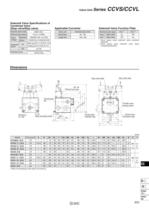
Valve Unit Series CCVS/CCVL Solenoid Valve Specifications of Combined Valve (Stop valve/Skip valve) Applicable Converter Solenoid Valve Function Plate t Valve opens when solenoid valve conducts * Valve opens when solenoid valve stops conducting electricity. * Pitch of mounting on the wall is CA and CL.
Open the catalog to page 11All SMC PNEUMATIC catalogs and technical brochures
 Vacuum Unit 2024
99 Pages
 Air Cylinder CJ2 Series
117 Pages
 AS-FS Series
36 Pages
 IDF series
12 Pages
 MHL2 Series
24 Pages
 JCM Serie
18 Pages
 EX245 Series
12 Pages
 Pin Cylinder CJP2/CDJP2/CJP
19 Pages
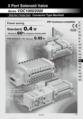 5 Port Solenoid Valve VQC
63 Pages
 5 Port Solenoid Valve VQ
79 Pages
 SY
SY268 Pages
 5-p0979-0980-hep500
2 Pages
 5-p0977-0978-aep100
2 Pages
 5-p0966-0971-lmu
5 Pages
 5-p0960-0966-alb900
6 Pages
 5-p0956-0960-ald600
5 Pages
 5-p0948-0950-al800
3 Pages
 es70-44c-vx2
52 Pages
 es50-37-kq2
124 Pages
 ex-pcw
23 Pages
 1-p2124-2152-ex510
29 Pages
 1-p2111-2122-ex500
12 Pages
 1-p2063-2073-ex260
11 Pages
 4-p0147-0178-msu-mds
32 Pages
 es20-230b-crb2
59 Pages
 1-p1869-1878-vp3145
10 Pages
 VP300/500/700 series
42 Pages
 1-p1789-1829-vqz100
41 Pages
 1-p1727-1788-syj300
62 Pages
 5 Port Solenoid Valve S0700
111 Pages
 5 Port Solenoid Valve VF
59 Pages
 5 Port Solenoid Valve SV
127 Pages
 VH
VH9 Pages
 CUJ
CUJ41 Pages
 AL
AL3 Pages
 kj mm
kj mm9 Pages
 AQ
AQ4 Pages
 SY3000/5000-X13
2 Pages
 Series MB
24 Pages
 Series LES
23 Pages
 Series LEFB
16 Pages
 Series PF3W
28 Pages
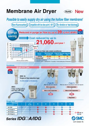 Series IDG?A/IDG
56 Pages
 Floating Joint
7 Pages
 Series IZS40/41/42
32 Pages
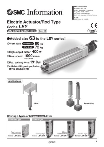 Series LEY
7 Pages
 Series VHS
12 Pages
 Series CY1S
28 Pages
 SeriesCQ2/CQS/CQ
4 Pages
 In-line Air Filter
12 Pages
 5 Port Solenoid Valve
60 Pages
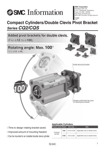 Series CQ2/CQS
2 Pages
 AS series
2 Pages
 corporate guide
13 Pages
 ZP
ZP69 Pages
 ZFA
ZFA14 Pages
 ZA
ZA13 Pages
 MHF
MHF32 Pages
 MHZ
MHZ68 Pages
 CRB
CRB44 Pages
 D
D117 Pages
 RB
RB23 Pages
 CEP
CEP44 Pages
 RSK
RSK30 Pages
 CLK
CLK51 Pages
 MK
MK20 Pages
 GLJ
GLJ65 Pages
 MGJ
MGJ7 Pages
 Mx
Mx36 Pages
 MXH
MXH18 Pages
 My3
My356 Pages
 my1b
my1b20 Pages
 J
J14 Pages
 CQ2
CQ251 Pages
 standard cylinder
84 Pages
 VFN
VFN6 Pages
 SY3000
246 Pages
 SJ3A6
SJ3A618 Pages
 1301/IW
14 Pages
 CHQ/CHDQ
19 Pages
 AC
AC95 Pages
 HAW
HAW4 Pages
 HAA
HAA3 Pages
 ZB
ZB24 Pages
 CRB2
CRB235 Pages


Archived catalogs
 CJ1
CJ15 Pages
 SYJ
SYJ62 Pages
 SJ
SJ78 Pages
 Vacuum Unit ZK2 Series
60 Pages
 SYJ300/500/700 Series
62 Pages
