- Catalogs
- SMC PNEUMATIC
- 5 Port Solenoid Valve VF
5 Port Solenoid Valve VF
1 /59Pages

5 Port Solenoid Valve VF
1 /59Pages
Catalog excerpts
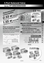
5 Port Solenoid Valve Series VF1000/3000/5000 wer d pon: uce it] ircu Red umptio ing c r sav owe cons ith p W Built-in full-wave rectifier (AC) Noise reduction Power consumption is reduced by power saving circuit. Power consumption is decreased by approx. 1/3 by reducing the wattage required to hold the valve in an energized state. (Effective energizing time is over 40 ms at 24 VDC.) Refer to electrical power waveform as shown below. Electrical power waveform with power saving circuit Noise is considerably reduced by changing it to DC mode with a full-wave rectifier. Reduced apparent power Conventional: 5.6 VA → 1.55 VA Built-in strainer in the pilot valve Unexpected troubles due to foreign matter can be prevented. Note) Be sure to mount an air filter on the inlet side. Applied voltage Power 0.35 W (Without light) consumption 0.4 W (With light) Low wattage specification added Rubber material: HNBR Ozone-resistant specification ∗ The pilot valve poppet is made of FKM. With power saving circuit
Open the catalog to page 1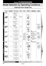
Model Selection by Operating Conditions q Solenoid Valve: Single Unit Series Port size Electrical entry Light/Surge voltage suppressor Manual override L-type plug connector Non-locking push type Body ported With surge voltage suppressor Base mounted With light/surge voltage suppressor Push-turn locking slotted type With surge voltage suppressor (Non-polar) With light/surge voltage suppressor (Non-polar) M-type plug connector With light/surge voltage suppressor Push-turn locking lever type Conduit terminal Power consumption: 0.35 W (Without light) 0.4 W (With light)
Open the catalog to page 2
Model Selection by Operating Conditions w Solenoid Valve: Manifold Series Manifold base model Applicable valve Applicable stations Body ported Base mounted
Open the catalog to page 3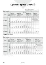
Cylinder Speed Chart q Use as a guide for selection. Please check the actual conditions with SMC Model Selection Program. Body Ported Bore size Series Series CJ2 Average Pressure 0.5 MPa speed Load factor 50% (mm/s) Stroke 60 mm ø6 Series CS1 Pressure 0.5 MPa Load factor 50% Stroke 1000 mm Series MB, CA2 Pressure 0.5 MPa Load factor 50% Stroke 500 mm Series CM2 Pressure 0.5 MPa Load factor 50% Stroke 300 mm Perpendicular, upward actuation Horizontal actuation : when using steel piping Base Mounted Bore size Series Series CJ2 Average Pressure 0.5 MPa speed Load factor 50% (mm/s) Stroke 60 mm ø6...
Open the catalog to page 4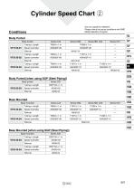
Cylinder Speed Chart w Use as a guide for selection. Please check the actual conditions with SMC Model Selection Program. Body Ported Body ported Speed controller Speed controller Speed controller Body Ported [when using SGP (Steel Piping)] Body ported Tubing x Length Speed controller Base Mounted Base mounted Speed controller Speed controller Base Mounted [when using SGP (Steel Piping)] Base mounted Speed controller Speed controller
Open the catalog to page 5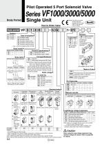
Pilot Operated 5 Port Solenoid Valve Series VF1000/3000/5000 Single Unit Body Ported How to Order Valve Body ported Note) Only DIN and conduit terminal types are available with AC mode. Refer to the electrical entry for details. Without bracket With bracket VF1000/3000 Single type (The bracket cannot be connected after delivered.) Standard (0.7 MPa) High-pressure type (1 MPa) 0: Pilot valve individual exhaust PE port∗ EA/EB port 3: Main/Pilot valve common exhaust VF1000 Double type only Coil specifications Body option Standard With power saving circuit (DC only) Note) Be sure to select the power...
Open the catalog to page 6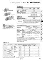
Pilot Operated 5 Port Solenoid Valve Body Ported/Single Unit Specifications Model Fluid Operating pressure range (MPa) 2-position single/3-position Standard 2-position double High2-position single/3-position pressure type 2-position double Ambient and fluid temperature (°C) Max. operating 2-position single/double frequency (Hz) 3-position Manual override Pilot exhaust type Lubrication Mounting orientation Impact/Vibration resistance (m/s2) Note) Enclosure Madeeto Made to Order Ord r Specification Pilot exhaust port with piping thread (M3) specification TRIAC output specification Type of actuation...
Open the catalog to page 7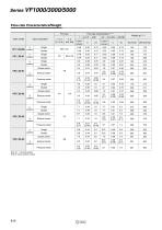
Series VF1000/3000/5000 Flow-rate Characteristics/Weight Port size Valve model Flow-rate characteristics Note 1) 1 → 4/2 (P → A/B) Closed center Pressure center Closed center Pressure center Closed center Pressure center Closed center Single Double Single Double Exhaust center Exhaust center Exhaust center Exhaust center Pressure center Note 1) [ ]: Normal position Note 2) Values without bracket
Open the catalog to page 8
Pilot Operated 5 Port Solenoid Valve Body Ported/Single Unit Construction: Body Ported 2-position single 3-position closed center/exhaust center/pressure center Symbol (Drawing shows a closed center type.) Description Body Adapter plate Spool valve Aluminum die-casted Resin Resin Resin Aluminum, HNBR Stainless steel Description Pilot valve assembly Refer to “How to Order Pilot Valve Assembly” on page 812. Built-in strainer Bracket Assembly Part No. Description Bracket (for VF1000 double) Part no. DXT144-8-1A (With 2 mounting screws)
Open the catalog to page 9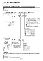
Series VF1000/3000/5000 How to Order Pilot Valve Assembly (With a gasket and two mounting screws) Caution When only the pilot valve assembly is replaced, it is not possible to change from V211 (Grommet or L/M-type) to V212 (DIN or Conduit type), or vice versa. Valve model: ∗ Select from the below in accordance with the valve used. 5 G Z Light/Surge voltage suppressor Nil Without light/surge voltage suppressor With surge voltage suppressor With light/surge voltage suppressor With surge voltage suppressor (Non-polar) With light/surge voltage suppressor (Non-polar) V211 Pilot valve assembly Note)...
Open the catalog to page 10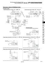
Pilot Operated 5 Port Solenoid Valve Body Ported/Single Unit Dimensions: Series VF1000/Body Ported 2-position single Grommet (G) (H): VF1120-G 1-M5(-F) H (Lead wire length) DC without light/surge voltage suppressor 2 x M4 x 0.7 thread depth 5 (For mounting) (Lead wire length) L-type plug connector (L): VF1120-L1-M5 (-F) DIN terminal (D) (Y): VF1120- D 1-M5(-F) 01 Y 01 Max. 10 Applicable cable O.D. ø4.5 to ø7 Approx. 300 (Lead wire length) (Indicator light) (Lead wire length) Manual override Unless otherwise indicated, dimensions are the same as Grommet (G). Unless otherwise indicated, dimensions...
Open the catalog to page 11All SMC PNEUMATIC catalogs and technical brochures
 Vacuum Unit 2024
99 Pages
 Air Cylinder CJ2 Series
117 Pages
 AS-FS Series
36 Pages
 IDF series
12 Pages
 MHL2 Series
24 Pages
 JCM Serie
18 Pages
 EX245 Series
12 Pages
 Pin Cylinder CJP2/CDJP2/CJP
19 Pages
 5 Port Solenoid Valve VQC
63 Pages
 5 Port Solenoid Valve VQ
79 Pages
 SY
SY268 Pages
 5-p0979-0980-hep500
2 Pages
 5-p0977-0978-aep100
2 Pages
 5-p0966-0971-lmu
5 Pages
 5-p0960-0966-alb900
6 Pages
 5-p0956-0960-ald600
5 Pages
 5-p0948-0950-al800
3 Pages
 es70-44c-vx2
52 Pages
 es50-37-kq2
124 Pages
 ex-pcw
23 Pages
 1-p2124-2152-ex510
29 Pages
 1-p2111-2122-ex500
12 Pages
 1-p2063-2073-ex260
11 Pages
 4-p0147-0178-msu-mds
32 Pages
 es20-230b-crb2
59 Pages
 1-p1869-1878-vp3145
10 Pages
 VP300/500/700 series
42 Pages
 1-p1789-1829-vqz100
41 Pages
 1-p1727-1788-syj300
62 Pages
 5 Port Solenoid Valve S0700
111 Pages
 5 Port Solenoid Valve SV
127 Pages
 VH
VH9 Pages
 CUJ
CUJ41 Pages
 AL
AL3 Pages
 kj mm
kj mm9 Pages
 AQ
AQ4 Pages
 SY3000/5000-X13
2 Pages
 Series MB
24 Pages
 Series LES
23 Pages
 Series LEFB
16 Pages
 Series PF3W
28 Pages
 Series IDG?A/IDG
56 Pages
 Floating Joint
7 Pages
 Series IZS40/41/42
32 Pages
 Series LEY
7 Pages
 Series VHS
12 Pages
 Series CY1S
28 Pages
 SeriesCQ2/CQS/CQ
4 Pages
 In-line Air Filter
12 Pages
 5 Port Solenoid Valve
60 Pages
 Series CQ2/CQS
2 Pages
 AS series
2 Pages
 corporate guide
13 Pages
 ZP
ZP69 Pages
 ZFA
ZFA14 Pages
 ZA
ZA13 Pages
 MHF
MHF32 Pages
 MHZ
MHZ68 Pages
 CRB
CRB44 Pages
 D
D117 Pages
 RB
RB23 Pages
 CEP
CEP44 Pages
 RSK
RSK30 Pages
 CLK
CLK51 Pages
 MK
MK20 Pages
 GLJ
GLJ65 Pages
 MGJ
MGJ7 Pages
 Mx
Mx36 Pages
 MXH
MXH18 Pages
 My3
My356 Pages
 my1b
my1b20 Pages
 CC
CC15 Pages
 J
J14 Pages
 CQ2
CQ251 Pages
 standard cylinder
84 Pages
 VFN
VFN6 Pages
 SY3000
246 Pages
 SJ3A6
SJ3A618 Pages
 1301/IW
14 Pages
 CHQ/CHDQ
19 Pages
 AC
AC95 Pages
 HAW
HAW4 Pages
 HAA
HAA3 Pages
 ZB
ZB24 Pages
 CRB2
CRB235 Pages


Archived catalogs
 CJ1
CJ15 Pages
 SYJ
SYJ62 Pages
 SJ
SJ78 Pages
 Vacuum Unit ZK2 Series
60 Pages
 SYJ300/500/700 Series
62 Pages
