- Catalogs
- SMC PNEUMATIC
- 5-p0960-0966-alb900
5-p0960-0966-alb900
1 /6Pages

5-p0960-0966-alb900
1 /6Pages
Catalog excerpts

Booster Lube Standard Specifications Centralized control of multi-point lubrication Stable oil feeding with a micromist pressure that is higher than that of the main air passage can be supplied. This difference is used as the mist generating pressure differential. Thus, the pressure drop in the main air passage is minimized. supplied by merely adjusting the mist generating pressure differential. opening and closing the oil filler plug without stopping the air line. Port (Bypass lubrication adapter) Port size (Body) of micromist can be checked from the oil filler port. 0.4 to 1.0 MPa Operating pressure differential range 0.05 to 0.2 MPa Bowl capacity between levels (cm3) 5000 Turbine oil Class 1 (With no additives), ISO VG32 Recommended lubricant Operating pressure range 5 to 50°C Epoxy resin with glass fiber, Polycarbonate Ambient and fluid temperature Bowl material Accessory (Option) Part No. Part no. Bypass lubrication adapter Standard accessory Ball valve Ball valve Float switch Note) Float switch specifications Voltage Max. contact capacity Max. contact current Contact Level indication 1a, 1b Bottom limit indication 0 0 Float switch (Option) Booster lube Operation control signal Body size Port size None Rc 1 Rc 2 3 inch flange None 1b (Without oil ON) 1a (Without oil OFF) Proof pressure
Open the catalog to page 1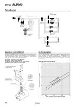
Piping Example Strainer Series AF-X2230 Solenoid valve Metal seal Ball valve Bypass lubrication adapter Ball valve Main line filter Series AFF Solenoid valve Rubber seal Operation Control Method As shown in the diagram below, reverse the position of the function plate of the switching valve for operation control, and place it in the NO position or in the unmarked position. When the control signal is input, select the state of the operation or the stopping of the Booster Lube. This unit uses a booster to generate a mist generating pressure differential. Therefore, the booster consumes and discharges...
Open the catalog to page 2
Booster Lube Setting of Mist Generation Pressure Differential Procedure 1. Obtain the air consumption flow rate in the downstream of the Booster Lube. 2. Obtain the necessary mist generation pressure differential from data(B). Data(B) Flow — Mist Generation Pressure Differential Precautions Be sure to read before handling. Refer to front matter 43 for Safety Instructions and pages 365 to 369 for Precautions on every series. Warning 1. Epoxy resin containing glass fiber and polycarbonate is used in some parts of the Booster Lube. The Booster Lube cannot be used in an environment or in a location...
Open the catalog to page 3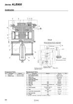
Circuit Manual switching valve for confirmation of mist generation pressure differential Lubrication plug 2 port valve Oil tank Mist generation nozzle Pressure differential Relay valve Switching valve for adjustment valve operation control Description Top cover Bottom cover Replacement Parts Material Aluminum casted Aluminum casted Description 3 port switching valve (for operation control) Relay valve Pressure gauge Diaphragm assembly Valve assembly NLP seal PNY seal Wear ring O-ring Bowl assembly Lubrication plug assembly NBR NBR Cloth-inserted phenol aldehyde resin NBR Glass fiber-inserted...
Open the catalog to page 4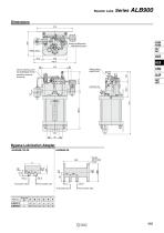
Booster Lube Pressure differential adjustment screw Relay valve Switching valve for operation control Manual switching valve for confirmation of mist generation pressure differential Lubrication plug Bypass Lubrication Adapter ALBA90-10/-20 From booster lube Port size Rc 1/2 From booster lube
Open the catalog to page 5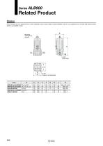
Related Product Strainer At the terminal of an air pressure line in which a Booster Lube is used, install a strainer (filtration rate of 5 µm) upstream from a metal seal solenoid valve, which is susceptible to dust. Mounting orientation is upward. 4xK Bracket mounting thread
Open the catalog to page 6All SMC PNEUMATIC catalogs and technical brochures
 Vacuum Unit 2024
99 Pages
 Air Cylinder CJ2 Series
117 Pages
 AS-FS Series
36 Pages
 IDF series
12 Pages
 MHL2 Series
24 Pages
 JCM Serie
18 Pages
 EX245 Series
12 Pages
 Pin Cylinder CJP2/CDJP2/CJP
19 Pages
 5 Port Solenoid Valve VQC
63 Pages
 5 Port Solenoid Valve VQ
79 Pages
 SY
SY268 Pages
 5-p0979-0980-hep500
2 Pages
 5-p0977-0978-aep100
2 Pages
 5-p0966-0971-lmu
5 Pages
 5-p0956-0960-ald600
5 Pages
 5-p0948-0950-al800
3 Pages
 es70-44c-vx2
52 Pages
 es50-37-kq2
124 Pages
 ex-pcw
23 Pages
 1-p2124-2152-ex510
29 Pages
 1-p2111-2122-ex500
12 Pages
 1-p2063-2073-ex260
11 Pages
 4-p0147-0178-msu-mds
32 Pages
 es20-230b-crb2
59 Pages
 1-p1869-1878-vp3145
10 Pages
 VP300/500/700 series
42 Pages
 1-p1789-1829-vqz100
41 Pages
 1-p1727-1788-syj300
62 Pages
 5 Port Solenoid Valve S0700
111 Pages
 5 Port Solenoid Valve VF
59 Pages
 5 Port Solenoid Valve SV
127 Pages
 VH
VH9 Pages
 CUJ
CUJ41 Pages
 AL
AL3 Pages
 kj mm
kj mm9 Pages
 AQ
AQ4 Pages
 SY3000/5000-X13
2 Pages
 Series MB
24 Pages
 Series LES
23 Pages
 Series LEFB
16 Pages
 Series PF3W
28 Pages
 Series IDG?A/IDG
56 Pages
 Floating Joint
7 Pages
 Series IZS40/41/42
32 Pages
 Series LEY
7 Pages
 Series VHS
12 Pages
 Series CY1S
28 Pages
 SeriesCQ2/CQS/CQ
4 Pages
 In-line Air Filter
12 Pages
 5 Port Solenoid Valve
60 Pages
 Series CQ2/CQS
2 Pages
 AS series
2 Pages
 corporate guide
13 Pages
 ZP
ZP69 Pages
 ZFA
ZFA14 Pages
 ZA
ZA13 Pages
 MHF
MHF32 Pages
 MHZ
MHZ68 Pages
 CRB
CRB44 Pages
 D
D117 Pages
 RB
RB23 Pages
 CEP
CEP44 Pages
 RSK
RSK30 Pages
 CLK
CLK51 Pages
 MK
MK20 Pages
 GLJ
GLJ65 Pages
 MGJ
MGJ7 Pages
 Mx
Mx36 Pages
 MXH
MXH18 Pages
 My3
My356 Pages
 my1b
my1b20 Pages
 CC
CC15 Pages
 J
J14 Pages
 CQ2
CQ251 Pages
 standard cylinder
84 Pages
 VFN
VFN6 Pages
 SY3000
246 Pages
 SJ3A6
SJ3A618 Pages
 1301/IW
14 Pages
 CHQ/CHDQ
19 Pages
 AC
AC95 Pages
 HAW
HAW4 Pages
 HAA
HAA3 Pages
 ZB
ZB24 Pages
 CRB2
CRB235 Pages


Archived catalogs
 CJ1
CJ15 Pages
 SYJ
SYJ62 Pages
 SJ
SJ78 Pages
 Vacuum Unit ZK2 Series
60 Pages
 SYJ300/500/700 Series
62 Pages
