- Catalogs
- SMC PNEUMATIC
- 1301/IW
1301/IW
1 /14Pages

1301/IW
1 /14Pages
Catalog excerpts
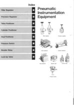
Filter Regulator Precision Regulator Valve Positioner Cylinder Positioner Dual Positioner Pressure Switch Booster Relay Lock-Up Valve Filter regulator Valve positioner Precision regulator Cylinder positioner Dual positioner Booster relay Lock-up valve Pressure switch
Open the catalog to page 2
Prevents moisture and dust in the compressed air line while maintaining pressure at a stable level, in spite of variations of both « Please specify port size;01 (/^)for series 1301, or 02(%)for series IW. Flow Characteristics Flow rate N£/min Pressure Characteristics
Open the catalog to page 3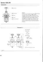
OAdjusting knob ©Adjusting spring OMain valve ©Sintered metal element Air flow from the inlet passes through element © where solids are removed. When adjusting knob O is adjusted downwards, adjusting spring @ is compressed. The main valve © is opened allowing air flow to the outlet. Air outlet pressure balances against diaphragm © and adjusting spring ©.When the outlet pressure is higher than the set pressure, the main valve © is closed and exhaust of the excess outlet pressure takes place through the adjusting spring cover bleed.This ensures constant outlet pressure is Gauge port Panel mounting...
Open the catalog to page 4
High sensitivity, excellent pressure accuracy beyond the scope of standard regulators. Suitable for applications requiring extremely precise pressure 3) Air consumption is due to exhaust from nozzle. 4) At 7kgf/cm2 of supply pressure. Pressure gauge Flow Characteristics Flow rate Nl/min Pressure Characteristics
Open the catalog to page 5
When knob O is turned downwards movement of adjusting spring © and diaphragm A © closes nozzle ®. Air flow from fixed orifice © causes a back pressure of nozzle ® which acts on diaphragm B 0. This causes downward movement of main valve @. Supply pressure can then flow to secondary supply. Pressure on diaphragm C 0 results in upward balancing movement of diaphragm B O and then A © against the spring force.When the secondary pressure increases, diaphragm A © is pushed upwards causing clearance between the flapper © and nozzle ®. Back pressure before nozzle is lowered. The imbalance of diaphragms...
Open the catalog to page 6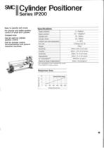
Easy to operate and mount. For precise and stable position control of smali bore cylinder. Compact size. position control. Unit for process control, industrial machines. üíAir consumption is due to exhaust from nozzle. Response time Cylinder bore size mm
Open the catalog to page 7
Above condition is at constant signal pressure i.e. cylinder is stopped. ©Input chamber ©Feedback spring When signal pressure enters input chamber O the diaphragm B © is deflected left. Clearance of the nozzle © is reduced causing higher back pressure at diaphragm A O. This diaphragm A O has larger area than diaphragm B © resulting in movement of the spool to the left. Supply pressure then flows to OUT 1 O and partial exhaust from OUT 2 takes place resulting in cylinder rod © movement to the right. The movement is linked via rod © and feedback spring @ to the input diaphragm © balancing the higher...
Open the catalog to page 8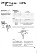
ressure Switch instrument process control with a combined function of controller High performance. Compact and light weight. Signal pressure Micro switch®— Adjusting screw© Signal pressure enters the chamber above diaphragm O and exerts downward force compressing spring ©. After sufficient deflection, contact with the plunger of the micro switch © is made operating the electrical circuit. As overtravel of diaphragm is prevented by an internal stop the micro switch is not subject to extra load with increased pressure. On decrease of signal pressure the electrical circuit function is reversed....
Open the catalog to page 9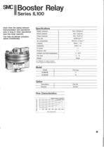
Used when the piping between area is long, or when operational area has large capacity. Can help accelerate actuation speed considerably. Flow Characteristics w/needie valve Flow rate Nl/min
Open the catalog to page 11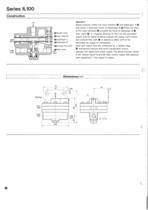
Signal pressure enters the input chamber © and diaphragm A @ and exerts a downward force on diaphragm B ®. When the force of the input chamber O exceeds the force of diaphragm B ®, main valve © is inseated allowing air flow out the secondary supply port. On signal pressure exhaust the supply valve closes and exhaust flow path © is opened to allow vent of the secondary air supply to atmosphere. Input and output ports are connected by a needle valve Q. Adjustment ensures that exact equalization occurs between the signal and output supply. The above function allows a low volume signal to provide...
Open the catalog to page 12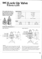
Lock-Up Valve When accident takes place on air operated process control line piping line, lock-up valve retains pressure at the tool end until restored to normal condition. Safe signal pressure enters the upper diaphragm chamber O and compresses the adjusting spring © and moves the upper diaphragm © upward.lt also closes the exhaust valve ©.Signal pressure also enters the lower diaphragm chamber @ and exerts a downward force on the valve ©. This opens the flow path from 'IN' and 'OUT' ports for flow in either direction. When malfunction in the control signal circuit occurs pressure holding the...
Open the catalog to page 13
• Blow out air lines and fittings before installation. • Use dry and oil-free air. Recommend use of SMC AM Mist
Open the catalog to page 14All SMC PNEUMATIC catalogs and technical brochures
 Vacuum Unit 2024
99 Pages
 Air Cylinder CJ2 Series
117 Pages
 AS-FS Series
36 Pages
 IDF series
12 Pages
 MHL2 Series
24 Pages
 JCM Serie
18 Pages
 EX245 Series
12 Pages
 Pin Cylinder CJP2/CDJP2/CJP
19 Pages
 5 Port Solenoid Valve VQC
63 Pages
 5 Port Solenoid Valve VQ
79 Pages
 SY
SY268 Pages
 5-p0979-0980-hep500
2 Pages
 5-p0977-0978-aep100
2 Pages
 5-p0966-0971-lmu
5 Pages
 5-p0960-0966-alb900
6 Pages
 5-p0956-0960-ald600
5 Pages
 5-p0948-0950-al800
3 Pages
 es70-44c-vx2
52 Pages
 es50-37-kq2
124 Pages
 ex-pcw
23 Pages
 1-p2124-2152-ex510
29 Pages
 1-p2111-2122-ex500
12 Pages
 1-p2063-2073-ex260
11 Pages
 4-p0147-0178-msu-mds
32 Pages
 es20-230b-crb2
59 Pages
 1-p1869-1878-vp3145
10 Pages
 VP300/500/700 series
42 Pages
 1-p1789-1829-vqz100
41 Pages
 1-p1727-1788-syj300
62 Pages
 5 Port Solenoid Valve S0700
111 Pages
 5 Port Solenoid Valve VF
59 Pages
 5 Port Solenoid Valve SV
127 Pages
 VH
VH9 Pages
 CUJ
CUJ41 Pages
 AL
AL3 Pages
 kj mm
kj mm9 Pages
 AQ
AQ4 Pages
 SY3000/5000-X13
2 Pages
 Series MB
24 Pages
 Series LES
23 Pages
 Series LEFB
16 Pages
 Series PF3W
28 Pages
 Series IDG?A/IDG
56 Pages
 Floating Joint
7 Pages
 Series IZS40/41/42
32 Pages
 Series LEY
7 Pages
 Series VHS
12 Pages
 Series CY1S
28 Pages
 SeriesCQ2/CQS/CQ
4 Pages
 In-line Air Filter
12 Pages
 5 Port Solenoid Valve
60 Pages
 Series CQ2/CQS
2 Pages
 AS series
2 Pages
 corporate guide
13 Pages
 ZP
ZP69 Pages
 ZFA
ZFA14 Pages
 ZA
ZA13 Pages
 MHF
MHF32 Pages
 MHZ
MHZ68 Pages
 CRB
CRB44 Pages
 D
D117 Pages
 RB
RB23 Pages
 CEP
CEP44 Pages
 RSK
RSK30 Pages
 CLK
CLK51 Pages
 MK
MK20 Pages
 GLJ
GLJ65 Pages
 MGJ
MGJ7 Pages
 Mx
Mx36 Pages
 MXH
MXH18 Pages
 My3
My356 Pages
 my1b
my1b20 Pages
 CC
CC15 Pages
 J
J14 Pages
 CQ2
CQ251 Pages
 standard cylinder
84 Pages
 VFN
VFN6 Pages
 SY3000
246 Pages
 SJ3A6
SJ3A618 Pages
 CHQ/CHDQ
19 Pages
 AC
AC95 Pages
 HAW
HAW4 Pages
 HAA
HAA3 Pages
 ZB
ZB24 Pages
 CRB2
CRB235 Pages


Archived catalogs
 CJ1
CJ15 Pages
 SYJ
SYJ62 Pages
 SJ
SJ78 Pages
 Vacuum Unit ZK2 Series
60 Pages
 SYJ300/500/700 Series
62 Pages
