- Catalogs
- SMC PNEUMATIC
- 1-p2124-2152-ex510
1-p2124-2152-ex510
1 /29Pages

1-p2124-2152-ex510
1 /29Pages
Catalog excerpts
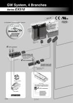
GW System, 4 Branches Series EX510 nit Compatible communication network ∗ Input units with covers 16-point input unit (interlinks 16 connectors) ∗ The product is shown without a cover. 16-point input unit (interlinks 8 connectors) ∗ The product is shown without a cover. Pressure switch Auto switch Two 2-wire auto switches can be connected to a single connector. connectors Flow switch
Open the catalog to page 1
it SI un ding Inclu ld valve o manif Output equipment Valve, indicator light, relay, buzzer, etc. can be connected. 2 port solenoid valve
Open the catalog to page 2
Features of Series EX510 Conventional Programmable logic controller Power supply Programmable logic controller Power supply Including SI unit manifold valve Input unit Including SI unit manifold valve Input unit Input unit Including SI unit manifold valve Input unit Including SI unit manifold valve Serial transmission system Input unit Input unit Including SI unit manifold valve Input unit Input unit Output unit Including SI unit manifold valve Including SI unit manifold valve More valves and sensors can be connected. • The introduction of the EX510 series makes it possible to connect more valves...
Open the catalog to page 3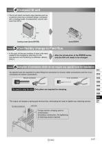
• The SI unit which connects output devices such as a solenoid valve has a compact design, compared with a existing model. (Compactness: volume ratio more than 60%) Existing model (Series EX120) Can flexibly change to Field Bus. • In the past, all the part numbers of slave units were needed to be changed by returning it to the manufacturer and reordering (re-estimate, delivery time) it. • After the introduction of the EX510 series, only the GW unit needs to be changed. Adoption of connectors which do not require any special tools for installation No special tools are required for press-fitting...
Open the catalog to page 4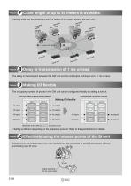
Cable length of up to 20 meters is available. Various units can be connected within a radius of 20 meters around the GW unit. ifold Man e valv Delay in transmission of 1 ms or less The delay in transmission between the GW unit and SI unit/Output unit/Input unit is 1 ms or less. The occupying number of points in the GW unit can be configured flexibly by setting a switch. 64 inputs/64 outputs (Initial setting) Making I/O flexible 16 inputs (Side view of the GW unit) ∗ Setting is different depending on the respective protocol. Refer to the specifications for details. Feature Effectively using the...
Open the catalog to page 5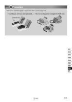
Each unit is protected against a short-circuit from a power supply load. Input/Output unit fuses are replaceable. The short circuit protection is integrated for the SI unit. Replaceable fuse
Open the catalog to page 6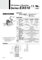
Communication protocol EX510-G MJ1 Power supply connector Specifications Model Applicable Protocol Version Note 1) system Communication connector Communication speed Configuration file Note 2) I/O occupation area (Inputs/Outputs) Terminating resistor Power For unit supply voltage For sensors For valve Internal current consumption Number of inputs Connection input device Supply voltage Supply current Number of outputs Connection output device Supply voltage Supply current Branch cable length Enclosure Operating temperature range Operating humidity range Withstand voltage Insulation resistance...
Open the catalog to page 7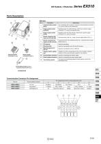
For connecting with a network, using the communication connector (!0), which is part of the accessories. Power supply socket (PWR(V)) Supplies power for output devices, which have a power supply connector (!1), such as a solenoid valve. Power supply socket (PWR) Supplies power for input devices, which have a power supply connector (!1), such as a sensor. Branch connector (for input) on GW unit side Connects input units, etc., using a branch cable (EX510-FC). Branch connector (for output) on GW unit side Connects the SI unit (manifold valves) etc., using the branch cable (EX510-FC). Mounting hole...
Open the catalog to page 8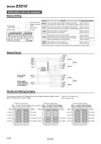
Series EX510 EX510-GMJ1 (CC-Link compliant) Display Setting Display HOLD/CLR setting Communication speed setting Indicator light condition The output power supply voltage is supplied as specified. Light is turned on. The output power supply voltage is not supplied as specified. Light is turned off. Mode setting Address setting Setting of occupied stations When the input and the power for the Gateway is being supplied. Light is turned on. When the input and the power for the Gateway is not being supplied. Light is turned off. Light is turned on. Light is turned off. When there is an error in the...
Open the catalog to page 9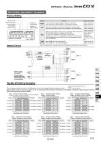
EX510-GDN1 (DeviceNet™ compliant) Display Setting HW/SW setting HOLD/CLR setting Number of input settings When the input and the power for the Gateway is being supplied. When the input and the power for the Gateway is not being supplied. Light is turned on. Light is turned off. When the power supply is OFF, off-line, or checking the MAC ID duplication. When I/O connection is on stand by. (On-line state) I/O connection installation is completed. (On-line state) I/O connection, time-out (communication irregularity in light degrees) MAC ID duplication error, or BUS OFF error (communication error...
Open the catalog to page 10
Series EX510 EX510-GPR1 (PROFIBUS DP compliant) Display Setting HOLD/CLR UNIT STATUS Indicator light condition Light is turned on. Light is turned off. When the input and the power for the Gateway is being supplied. When the input and the power for the Gateway is not being supplied. Light is turned on. Light is turned off. When the extended diagnostic information is available. When the extended diagnostic informatiion is not available. Light is turned on. Light is turned off. When PROFIBUS DP communication is working improperly. When PROFIBUS DP communication is working properly. Light is turned...
Open the catalog to page 11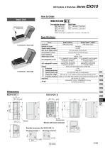
How to Order Input Unit 1 connector, 2-input type 1 connector, 1 input type Note) B (2-wire type) is available with 1 connector, 2-input type only. Model Input type Sensor supply voltage Max. sensor supply current Consumption current 100 mA (Input unit internal parts) Input resistance Rated input current Approx. 4 mA 17 V or greater/2.5 mA or greater 17 V or greater/2.5 mA or greater (Between input terminal and for sensor + 24 VDC) (Between input terminal and for sensor + 24 VDC) 1 connector, 1 input type (Between input terminal and for sensor 0 VDC) (Between input terminal and for sensor 0 VDC)...
Open the catalog to page 12All SMC PNEUMATIC catalogs and technical brochures
 Vacuum Unit 2024
99 Pages
 Air Cylinder CJ2 Series
117 Pages
 AS-FS Series
36 Pages
 IDF series
12 Pages
 MHL2 Series
24 Pages
 JCM Serie
18 Pages
 EX245 Series
12 Pages
 Pin Cylinder CJP2/CDJP2/CJP
19 Pages
 5 Port Solenoid Valve VQC
63 Pages
 5 Port Solenoid Valve VQ
79 Pages
 SY
SY268 Pages
 5-p0979-0980-hep500
2 Pages
 5-p0977-0978-aep100
2 Pages
 5-p0966-0971-lmu
5 Pages
 5-p0960-0966-alb900
6 Pages
 5-p0956-0960-ald600
5 Pages
 5-p0948-0950-al800
3 Pages
 es70-44c-vx2
52 Pages
 es50-37-kq2
124 Pages
 ex-pcw
23 Pages
 1-p2111-2122-ex500
12 Pages
 1-p2063-2073-ex260
11 Pages
 4-p0147-0178-msu-mds
32 Pages
 es20-230b-crb2
59 Pages
 1-p1869-1878-vp3145
10 Pages
 VP300/500/700 series
42 Pages
 1-p1789-1829-vqz100
41 Pages
 1-p1727-1788-syj300
62 Pages
 5 Port Solenoid Valve S0700
111 Pages
 5 Port Solenoid Valve VF
59 Pages
 5 Port Solenoid Valve SV
127 Pages
 VH
VH9 Pages
 CUJ
CUJ41 Pages
 AL
AL3 Pages
 kj mm
kj mm9 Pages
 AQ
AQ4 Pages
 SY3000/5000-X13
2 Pages
 Series MB
24 Pages
 Series LES
23 Pages
 Series LEFB
16 Pages
 Series PF3W
28 Pages
 Series IDG?A/IDG
56 Pages
 Floating Joint
7 Pages
 Series IZS40/41/42
32 Pages
 Series LEY
7 Pages
 Series VHS
12 Pages
 Series CY1S
28 Pages
 SeriesCQ2/CQS/CQ
4 Pages
 In-line Air Filter
12 Pages
 5 Port Solenoid Valve
60 Pages
 Series CQ2/CQS
2 Pages
 AS series
2 Pages
 corporate guide
13 Pages
 ZP
ZP69 Pages
 ZFA
ZFA14 Pages
 ZA
ZA13 Pages
 MHF
MHF32 Pages
 MHZ
MHZ68 Pages
 CRB
CRB44 Pages
 D
D117 Pages
 RB
RB23 Pages
 CEP
CEP44 Pages
 RSK
RSK30 Pages
 CLK
CLK51 Pages
 MK
MK20 Pages
 GLJ
GLJ65 Pages
 MGJ
MGJ7 Pages
 Mx
Mx36 Pages
 MXH
MXH18 Pages
 My3
My356 Pages
 my1b
my1b20 Pages
 CC
CC15 Pages
 J
J14 Pages
 CQ2
CQ251 Pages
 standard cylinder
84 Pages
 VFN
VFN6 Pages
 SY3000
246 Pages
 SJ3A6
SJ3A618 Pages
 1301/IW
14 Pages
 CHQ/CHDQ
19 Pages
 AC
AC95 Pages
 HAW
HAW4 Pages
 HAA
HAA3 Pages
 ZB
ZB24 Pages
 CRB2
CRB235 Pages


Archived catalogs
 CJ1
CJ15 Pages
 SYJ
SYJ62 Pages
 SJ
SJ78 Pages
 Vacuum Unit ZK2 Series
60 Pages
 SYJ300/500/700 Series
62 Pages
