- Catalogs
- SMC PNEUMATIC
- 1-p2063-2073-ex260
1-p2063-2073-ex260
1 /11Pages

1-p2063-2073-ex260
1 /11Pages
Catalog excerpts

Fieldbus System Series EX260 (Output device for driving 5 port solenoid valves) ® Space-saving Installation ∗ For units with D-sub connector, and when connected to S0700 manifolds, it is IP40. Drives up to 32 solenoids Daisy-chain wiring communication Bottom ported valve Side ported valve Mixed valve sizes manifold
Open the catalog to page 1
Manifold length is shortened by the small fieldbus output module (SI unit). Wiring and piping from the same direction is possible. (for side ported) Effective for installation in locations where space is limited above the valve. External branch connector is not necessary. Daisy-chain wiring is possible. Reduced wiring space EX260 Branch connector External terminating resistor is not necessary. (Only available for M12 PROFIBUS DP, CC-Link communication connectors) ON/OFF switching is possible with an internal terminating resistor. External terminating resistor is not necessary. Product Specification...
Open the catalog to page 2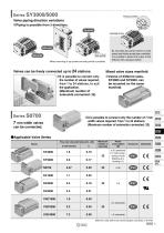
Pressure switch Valve piping direction variations Piping is possible from 3 directions. Top ported Bottom ported Side ported By mounting top ported valves on side ported and bottom ported type manifolds, it is possible to detect the output of the A/B port with a pressure switch. Side ported Mixed mounting of top ported and side ported is possible. Valves can be freely connected up to 24 stations. Mixed valve sizes manifold It is possible to connect only the number of valves required, from 1 to 24 stations, to suit the application. (Maximum number of solenoids connected: 32) Valves of different...
Open the catalog to page 3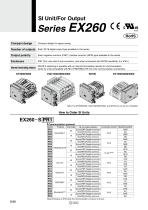
Series EX260 Compact design Compact design for space saving Number of outputs Each 32/16 digital output type available in the series Output polarity Each negative common (PNP) / positive common (NPN) type available in the series IP67 (For units with D-sub connector, and when connected with S0700 manifolds, it is IP40.) ON/OFF switching is possible with an internal terminating resistor for communication. Internal terminating resistor (Only for units compatible with M12 PROFIBUS DP, CC-Link communication connectors) SY3000/5000 EX260 S PR1 Communication protocol Symbol Communication connector SI...
Open the catalog to page 4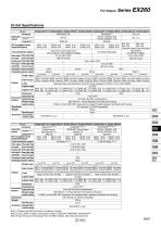
SI Unit Specifications Model Protocol Applicable system Configuration file Note 3) I/O occupation area (Inputs/Outputs) Communication speed Power supply Power supply voltage Internal current consumption for control Power supply for output Power supply voltage Power supply for Power supply voltage communication Internal current consumption Communication connector specification Terminating resistor switch DeviceNet™ Volume 1(Edition 3.5) Volume 3(Edition 1.5) EDS file None Sink/NPN Built-in Source/PNP Output type (Negative common) (Positive common) (Negative common) (Positive common) (Negative...
Open the catalog to page 5
Series EX260 SI Unit Dimensions D-sub communication connector type M12 communication connector type Functions of SI Unit Parts • Address switch • Communication speed switch • Terminating resistor switch • Others Note) The setting switch varies depending on the model. Refer to the operation manual for details. Please download it via the SMC website, http://www.smcworld.com • Communication state • Unit power supply state • Valve power supply state Communication protocol 5 pins, socket, A code 5 pins, socket, A code EtherCAT PROFINET EtherNet/IP™ 4 pins, socket, D code 4 pins, plug, A code 4 pins,...
Open the catalog to page 6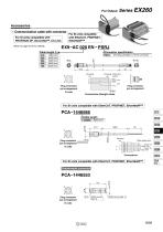
Accessories q Communication cable with connector For SI units compatible with PROFIBUS DP, DeviceNet™, CC-Link For SI units compatible with EtherCAT, PROFINET, EtherNet/IP™ EX9 AC 020 EN PSRJ Connector specification M12 plug (straight) ⇔ RJ-45 connector 45 Terminal Core wire colors no. Plug connector pin arrangement D code Plug connector pin arrangement Connections (Straight cable) For SI units compatible with EtherCAT, PROFINET, EtherNet/IP™ Cable length M12 Plug connector pin arrangement SPEEDCON Wire guide color Yellow: TD+ White: RD+ Orange: TD– Blue: RD– Fieldwireable connector Plug connector...
Open the catalog to page 7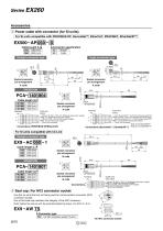
Series EX260 Accessories w Power cable with connector (for SI units) For SI units compatible with PROFIBUS DP, DeviceNet™, EtherCAT, PROFINET, EtherNet/IP™ Straight Angle Straight connector type Core wire colors Brown: Not connected Note 1), 24 VDC ±10% (Control power supply) Note 2) White: 24 VDC +10%/–5% (Solenoid valve power supply) Blue: Not connected Note 1), 0 V (Control power supply) Note 2) Black: 0 V (Solenoid valve power supply) Gray: Not connected Connections (DeviceNet™, EtherNet/IP™) Note 2) For EtherNet/IP™ L Straight connector type 2 3 Socket connector pin arrangement Socket connector...
Open the catalog to page 8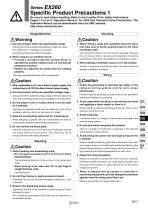
EX260 Specific Product Precautions 1 Be sure to read before handling. Refer to front matter 53 for Safety Instructions, Pages 3 to 8 and “Operation Manual” for 3/4/5 Port Solenoid Valve Precautions. The Operation Manual can be downloaded from the SMC website, http://www.smcworld.com Design/Selection 1. Use this product within the specification range. Using beyond the specified specifications range can cause fire, malfunction, or damage to the system. Check the specifications before operation. 2. When using for an interlock circuit: • Provide a multiple interlock system which is operated by another...
Open the catalog to page 9
EX260 Specific Product Precautions 2 Be sure to read before handling. Refer to front matter 53 for Safety Instructions, Pages 3 to 8 and “Operation Manual” for 3/4/5 Port Solenoid Valve Precautions. The Operation Manual can be downloaded from the SMC website, http://www.smcworld.com Wiring Operating Environment 8. When connecting wires of output device, prevent water, solvent or oil from entering inside the connector section. 2. Provide adequate protection when operating in locations such as the following. Caution This can cause damage, equipment failure or malfunction. 9. Avoid wiring patterns...
Open the catalog to page 10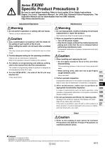
EX260 Specific Product Precautions 3 Be sure to read before handling. Refer to front matter 53 for Safety Instructions, Pages 3 to 8 and “Operation Manual” for 3/4/5 Port Solenoid Valve Precautions. The Operation Manual can be downloaded from the SMC website, http://www.smcworld.com Adjustment/Operation Warning 1. Do not perform operation or setting with wet hands. There is a risk of electrical shock. Warning 1. Do not disassemble, modify (including circuit board replacement) or repair this product. Such actions are likely to cause injuries or breakage. Caution 1. Use a watchmakers’ screwdriver...
Open the catalog to page 11All SMC PNEUMATIC catalogs and technical brochures
 Vacuum Unit 2024
99 Pages
 Air Cylinder CJ2 Series
117 Pages
 AS-FS Series
36 Pages
 IDF series
12 Pages
 MHL2 Series
24 Pages
 JCM Serie
18 Pages
 EX245 Series
12 Pages
 Pin Cylinder CJP2/CDJP2/CJP
19 Pages
 5 Port Solenoid Valve VQC
63 Pages
 5 Port Solenoid Valve VQ
79 Pages
 SY
SY268 Pages
 5-p0979-0980-hep500
2 Pages
 5-p0977-0978-aep100
2 Pages
 5-p0966-0971-lmu
5 Pages
 5-p0960-0966-alb900
6 Pages
 5-p0956-0960-ald600
5 Pages
 5-p0948-0950-al800
3 Pages
 es70-44c-vx2
52 Pages
 es50-37-kq2
124 Pages
 ex-pcw
23 Pages
 1-p2124-2152-ex510
29 Pages
 1-p2111-2122-ex500
12 Pages
 4-p0147-0178-msu-mds
32 Pages
 es20-230b-crb2
59 Pages
 1-p1869-1878-vp3145
10 Pages
 VP300/500/700 series
42 Pages
 1-p1789-1829-vqz100
41 Pages
 1-p1727-1788-syj300
62 Pages
 5 Port Solenoid Valve S0700
111 Pages
 5 Port Solenoid Valve VF
59 Pages
 5 Port Solenoid Valve SV
127 Pages
 VH
VH9 Pages
 CUJ
CUJ41 Pages
 AL
AL3 Pages
 kj mm
kj mm9 Pages
 AQ
AQ4 Pages
 SY3000/5000-X13
2 Pages
 Series MB
24 Pages
 Series LES
23 Pages
 Series LEFB
16 Pages
 Series PF3W
28 Pages
 Series IDG?A/IDG
56 Pages
 Floating Joint
7 Pages
 Series IZS40/41/42
32 Pages
 Series LEY
7 Pages
 Series VHS
12 Pages
 Series CY1S
28 Pages
 SeriesCQ2/CQS/CQ
4 Pages
 In-line Air Filter
12 Pages
 5 Port Solenoid Valve
60 Pages
 Series CQ2/CQS
2 Pages
 AS series
2 Pages
 corporate guide
13 Pages
 ZP
ZP69 Pages
 ZFA
ZFA14 Pages
 ZA
ZA13 Pages
 MHF
MHF32 Pages
 MHZ
MHZ68 Pages
 CRB
CRB44 Pages
 D
D117 Pages
 RB
RB23 Pages
 CEP
CEP44 Pages
 RSK
RSK30 Pages
 CLK
CLK51 Pages
 MK
MK20 Pages
 GLJ
GLJ65 Pages
 MGJ
MGJ7 Pages
 Mx
Mx36 Pages
 MXH
MXH18 Pages
 My3
My356 Pages
 my1b
my1b20 Pages
 CC
CC15 Pages
 J
J14 Pages
 CQ2
CQ251 Pages
 standard cylinder
84 Pages
 VFN
VFN6 Pages
 SY3000
246 Pages
 SJ3A6
SJ3A618 Pages
 1301/IW
14 Pages
 CHQ/CHDQ
19 Pages
 AC
AC95 Pages
 HAW
HAW4 Pages
 HAA
HAA3 Pages
 ZB
ZB24 Pages
 CRB2
CRB235 Pages


Archived catalogs
 CJ1
CJ15 Pages
 SYJ
SYJ62 Pages
 SJ
SJ78 Pages
 Vacuum Unit ZK2 Series
60 Pages
 SYJ300/500/700 Series
62 Pages
