- Products
- Catalogs
- News & Trends
- Exhibitions
ZA
1 /13Pages

ZA
1 /13Pages
Catalog excerpts

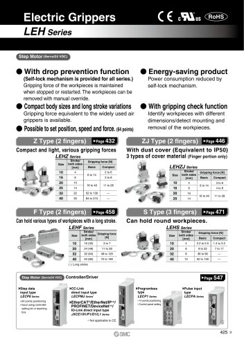
Compact Vacuum Ejector Possible to be mounted on moving parts thanks to lightweight Shortened tube length response time improved. 2 kinds of pressure range • Nominal filtration rating: 30 urn
Open the catalog to page 1
Compact Vacuum Ejector Ejector Unit Nozzle nominal size Solenoid valve combination (Refer to Table (1). Pilot valve (Refer to Table (1).) Note) Avoid energizing the solenoid valve for long periods of time. (Refer to Design and Selection on Specific Product Precautions 1.) Power supply voltage (Refer to Table (1).)1 Electrical entry Air pressure supply (P) port Note) O-ring and round head combination screws (M2 x 12) are attached to the supply adapter (M). Pressure sensor specifications Note 1) One-touch fittings are plugged when the pressure sensor is Note 2) This pressure switch detects pressure...
Open the catalog to page 2
Compact Vacuum Ejector Seríes Maximum Simultaneous Opreating Stations Manifold Ordering Example Blanking plate assembly Note) The stations are sequentially numbered. When viewed from the side of the vacuum ports, the far left station is designated as station 1. Right common air pressure supply (P) port (viewed from the vacuum (V) port side) Blanking plate assembly Left common air pressure supply (P) port (viewed from the vacuum (V) port side) Flow Characteristics / Exhaust Characteristics Suction flow Suction flow (tfmin(ANR))
Open the catalog to page 3
General Specifications Note) There was no malfunction confirmed when tested under the following conditions: From 10 to 500 to 10 Hz and whichever of the following is smaller: 1.5 mm amplitude or 98 m/s2 acceleration in X, Y, Z direction for 2 hours each, (initial value) Note) The maximum vacuum pressure was determined by applying the standard supply pressure. Different supply pressures are required to determine a model. • Calculation of mass for the manifold type (Single unit mass) x (Number of stations) Example) 5 stations manifold with pressure Pressure Sensor
Open the catalog to page 4
Compact Vacuum Ejector Seríes Component Parts Replacement Parts ■ For above parts of No. 7 and No. 11, the parts assembly ZA1-OP-1 (10 pes each) is Solenoid Valve Solenoid valve connector assembly Pilot valve Rated coil voltage < Manual override Electrical entry How to order connector assembly Connector, socket (3 pes) only 'Lead wire length • Lead-wire length of the plug connector The lead-wire length for a valve with a lead-wire is 300 mm. When in need of a valve with a lead-wire longer than 600 mm, place an order for a valve without a con- nector and connector assembly. Vacuum Pressure Switch...
Open the catalog to page 5
Release flow adjusting needle Locking type manual override Circuit diagram (Mounting hole) Note) When the body is mounted, tighten Using excessive torque may cause Supply pilot valve Locking type manual override Locking type manual override Supply pilot valve Dimensions of the vacuum (V) and air pressure supply (P) port fittings after installation Dimensions after the fittings are installed on the vacuum (V) port, air pressure supply (P) port of a single unit, and the common air pressure supply (P) port of a manifold are shown below. Dimensions of the vacuum (V) port fittings after installation...
Open the catalog to page 6
Compact Vacuum Ejector Release flow adjusting needle Circuit diagram Supply adapter Supply pilot valve Suction filter (Mounting hole) Supply pilot valve Supply pilot valve Note) When the body is mounted, tighten Using excessive torque may cause Dimensions of the vacuum (V) and air pressure supply (P) port fittings after installation Dimensions after the fittings are installed on the vacuum (V) port, air pressure supply (P) port of a single unit, and the common air pressure supply (P) port of a manifold are shown below. Dimensions of the vacuum (V) port fittings after installation Applicable tubing...
Open the catalog to page 7
P0849-P0936-E.qxd 08.9.30 2:41 PM Page 856 Series ZA re t ssu por pre (P) Air pply su Dimensions um cu Va 0 B A 1 1 Q1 N1 ZA1 Plug rt po (V) Type Release flow adjusting needle 76.9 78 Q1 N1 ZA1 1 Q1 N1 B Supply pilot valve Release valve Air pressure supply (P) port Vacuum (V) port V ZA1 1 Q1 N1 V FP 5 Approx. 3000 Suction filter 9 P 10 6.4 57.5 M3 23 Supply adapter 2 x ø2.7 (Mounting hole) 10 9.9 5.2 B ZA1 Circuit diagram Q1 N1 1 L FP Note) When the body is mounted, tighten with a torque of 0.6 ± 0.06 N·m. Using excessive torque may cause damage to the body. 02 Vacuum release valve 24.7 Supply...
Open the catalog to page 8
Compact Vacuum Ejector Release flow adjusting needle Circuit diagram Supply pilot valve Supply pilot valve Supply adapter (Mounting hole) Note) When the body is mounted, tighten Using excessive torque may cause Dimensions of the vacuum (V) and air pressure supply (P) port fittings after installation Dimensions after the fittings are installed on the vacuum (V) port, air pressure supply (P) port of a single unit, and the common air pressure supply (P) port of a manifold are shown below. Dimensions of the vacuum (V) port fittings after installation Air pressure supply (P) port \ Air pressure supply...
Open the catalog to page 9
Manifold type (Common SUP) Supply pilot valve Note 1 ) The above dimensions are for ZZA103-00. Note 2) When the body is mounted, tighten with a Using excessive torque may cause damage Note 3) When viewed from the manifold base, count the number of stations 1, 2 to (n) beginning from the left side. Dimensions of the vacuum (V) and air pressure supply (P) port fittings after installation Dimensions after the fittings are installed on the vacuum (V) port, air pressure supply (P) port of a single unit, and the common air pressure supply (P) port of a manifold are shown below. Applicable tubing Dimensions...
Open the catalog to page 10
P0849-P0936-E.qxd 08.9.30 2:41 PM Page 859 Compact Vacuum Ejector Series ZA Manifold Type: How to Increase / Decrease Manifold Stations ZA ZX ZR ZM Blanking plate assembly ZA1-BP1 ∗ (O-ring and round head combination screws (M2 x 12) are attached.) ZMA ZQ ZH ZU ZL ZY ZF Manifold base ZZA10- ZP SP ∗ An assembly kit (part no. ZA1-OP-1) is available which includes 10 pcs each of O-rings and round head combination screws. ZCUK AMJ AMV AEP HEP Related Equipment 859
Open the catalog to page 11All SMC Corporation of America catalogs and technical brochures
 LEHZ
LEHZ67 Pages
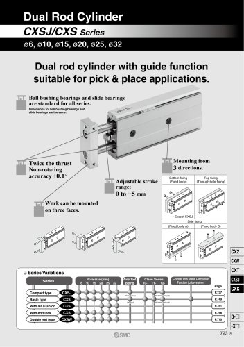 CXSJ
CXSJ60 Pages
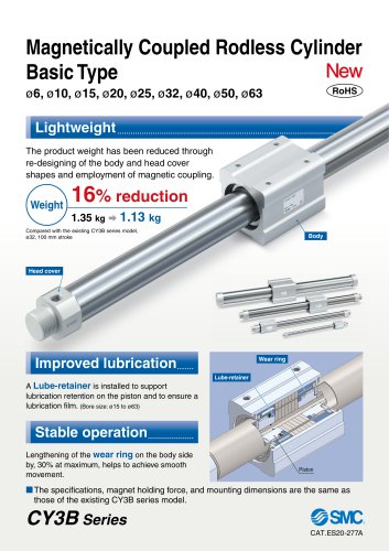 CY3B
CY3B17 Pages
 Aluminum High Vacuum Angle Valve
26 Pages
 AP Ultra High Purity
25 Pages
 IFW5 series
5 Pages
 Air Management System
64 Pages
 25A-ZSE20(F)/ISE20 Series
12 Pages
 ASG
ASG4 Pages
 IDG
IDG49 Pages
 CXSJ_M
2 Pages
 JLV20/30
8 Pages
 Series NCQ2/CQ2
252 Pages
 AC Series - Modular F.R.L. Units
70 Pages
 KQG2
KQG218 Pages
 IDF*E
IDF*E48 Pages
 AC10-A to AC40-A
82 Pages
 VQZ115, 100 Series
41 Pages
 SYJ300
60 Pages
 3000 Series
272 Pages
 MTS8
MTS823 Pages
 CXS-A
CXS-A60 Pages
 CXSL
CXSL60 Pages
 MXQR
MXQR36 Pages
 NC(D)Q2-Z
252 Pages
 LEY series
88 Pages
 MXH series
18 Pages
 KQ2
KQ2214 Pages
 Modular F.R.L. Units
108 Pages
 MXQ series
198 Pages
 Fieldbus System
92 Pages
 Fluoropolymer Piping Equipment
82 Pages
 Digital Flow Switch
24 Pages
 Vacuum Pad with Ejector
8 Pages
 Intrinsically safe Valve
43 Pages
 CQ2 series
25 Pages
 IDH, Thermo-dryer
12 Pages
 ISG
ISG10 Pages
 ISE3
ISE38 Pages
 ISE2
ISE27 Pages
 ISE1
ISE15 Pages
 ISA
ISA59 Pages
 IS3000
2 Pages
 IS10/10M/10E
4 Pages
 PSE series
44 Pages
 ISE70/75/75H
10 Pages
 ISE80
ISE8017 Pages
 ISE40A
29 Pages
 HED series
16 Pages
 HEC series
32 Pages
 HEB series
9 Pages
 HRG series
85 Pages
 HRZ series
52 Pages
 HRW series
28 Pages
 LQ series
35 Pages
 LVQ series catalog
75 Pages
 PA series
37 Pages
 EX600, Analog Input/Output Unit
59 Pages
 LER series
62 Pages
 LEJ series
58 Pages
 ISE/ZSE30A series
18 Pages
 LAT3 series
24 Pages
 LEH series
103 Pages
 CQS series
59 Pages
 CH series
175 Pages
 ARX series
12 Pages
 HRS series
47 Pages
 LES
LES59 Pages
 MHS
MHS74 Pages
 MHY
MHY27 Pages
 MHC
MHC27 Pages
 MHR
MHR30 Pages
 MHZ series
78 Pages
 MSQ
MSQ37 Pages
 MGP
MGP127 Pages
 MXS
MXS38 Pages
 NRB
NRB10 Pages
 MXW
MXW22 Pages
 MHT
MHT11 Pages
 MY3
MY354 Pages
 CQM
CQM15 Pages
 NCA1
NCA163 Pages
 CM2
CM2152 Pages
 NCM
NCM91 Pages
 NCG
NCG96 Pages
 NCRA1
NCRA15 Pages
 CS2
CS232 Pages
 T/TIA
T/TIA1 Page
 KR
KR7 Pages
 KF
KF16 Pages
 KQ
KQ80 Pages
 AFF
AFF80 Pages
 AMG
AMG80 Pages
 IDF
IDF16 Pages
 HAA
HAA3 Pages
 ZFA
ZFA14 Pages
 MHF
MHF32 Pages
 CRB
CRB44 Pages
 D
D117 Pages
 RB
RB23 Pages
 CEP
CEP44 Pages
 rsq
rsq30 Pages
 CLK
CLK51 Pages
 MK
MK20 Pages
 CLJ
CLJ65 Pages
 MGJ
MGJ7 Pages
 ZSE30A
17 Pages
 IDFB*E
89 Pages
 ISE10
ISE1016 Pages
 ITV1000/2000
50 Pages
 AW
AW27 Pages
 NVFM200
12 Pages
 NVM100
32 Pages
 LLA*A
LLA*A36 Pages
 VX3*
VX3*41 Pages
 SY3000
158 Pages
 CH(D)2
175 Pages
 M(D)SUB
31 Pages


Archived catalogs
 Rodless cylinder
52 Pages
 ZSE1 series
12 Pages
 Rack and Pinion Rotary Actuators
37 Pages
 Special Fittings
14 Pages
 Toggle Grippers
16 Pages
 SX series
138 Pages
 ACG series
25 Pages
 C95 Pneumatic Cylinder
50 Pages
 Shock Absorber
16 Pages
 Silencer
4 Pages
 VV061 series
11 Pages
 Air Filter Catalog
18 Pages
 heavy Duty Actuators
88 Pages
 Self-seal Fittings Catalog
13 Pages
 Connectors Catalog
53 Pages

