- Catalogs
- SMC Corporation of America
- VV061 series
VV061 series

VV061 series
Catalog excerpts

Unit Manifold Valve Compact Direct Operated 3 Port Solenoid Valve 5 31. 8 stations 4 stations 26 38 Weight: 38.6 Weight: 75g 47g ∗ When a bracket is not included, barb fittings are included. lveies va 6 th 0 ser wid 06 mmg the V n unt o i M Printed circuit board V060 Valve, PCB, base and fittings are fully integrated, forming a single compact unit. New concept unit manifold Series VV061 Base Fitting ∗ Photo shown depicts an 8-station unit manifold. CAT.ES11-92A
Open the catalog to page 1
dlloffiinaM ttiinU d o naM nU One-touch fitting and barb fitting can be selected. One-touch fitting ø2 Mounting • Bracket mount • Panel mount Barb fitting ø4/ø2.5 Bracket Panel mount example Lead wire length In case of 8 stations 1(P) 3(R) 2(A) 2(A) Connector cable Length: 300 mm 600 mm 1000 mm No.8 No.7 2(A) 2(A) No.6 No.5 2(A) 2(A) No.4 No.3 2(A) 2(A) No.2 Reduced environmental impact substance RoHS compliant Features 1 No.1
Open the catalog to page 2
Unit Manifold Valve Compact Direct Operated 3 Port Solenoid Valve Valve stations Port size Barb fitting Note) The applicable tube of the barb fitting shows the tube outside diameter/inside Rated voltage* Coil specifications Standard (With light/surge voltage suppressor) With power-saving circuit (Continuous duty type) If the coil will be continuously energized for a long period, be sure to choose the coil with power-saving circuit. (See the back page 2 for details.) (2 mounting screws M2 x 27 are included.] Connector cable Nil: Without connector cable C1: With connector cable (Length 300 mm)...
Open the catalog to page 3
Unit Manifold Specifications Note 1) Based on dynamic performance test, JIS B8374-1981. (Standard type: Coil temperature 20°C, at rated Note 2) Impact resistance: No malfunction occurred when it is tested with a drop tester in the axial direction and at the right angles to the main valve and armature in both energized and de- energized states every once for each condition. (Value in the initial state) Vibration resistance: No malfunction occurred in one sweep test between 45 and 2000 Hz. Test was performed to axis and right angle directions of the main valve and armature when pilot signal is...
Open the catalog to page 4
Compact Direct Operated 3 Port Solenoid Valve Series VV061 Unit Manifold Internal Wiring In case of 4 stations In case of 8 stations Groove (2 locations) Groove (2 locations) 1 3 5 1 3 5 7 9 2 4 6 2 4 6 8 10 Station 8 Station 7 Station 6 Station 5 Station 4 Station 3 Station 2 Positive polarity (common) Station 1 Station 4 Station 3 Station 2 Terminal no. Station 1 Terminal no. Positive polarity (common) Connector Cable Specifications 9 10 Connector Cable Color List of Each Terminal No. 12 In case of 4 stations In case of 8 stations Lead wire color Brown 1 Brown Red 2 Red 3 Orange 3 Orange 4...
Open the catalog to page 5
Replacement Parts CD Unit Assembly Part No. Valve stations * Rated voltage Coil specifications Nil Standard (With light/surge voltage suppressor) With power-saving circuit (Continuous duty type) * If the coil will be continuously energized for a long period, be sure to choose the coil with power-saving circuit. Operating pressure range High flow type (0 to 0.3 MPa) ■ 4 mounting screws (M2 x 27 L) and one gasket are included CD Plate Assembly Part No. Barb fitting Barb fitting is included. One-touch fitting One-touch fitting is mounted on If only the fitting is needed, order with one of the part...
Open the catalog to page 6
Compact Direct Operated 3 Port Solenoid Valve Series VV061 Dimensions VV061-04 LED indicator 38.6 32.6 6 Solenoid valve No. Solenoid valve No. 3 1 2 3 4 No. 4 No. 2 4 3 2 1 6 26 21.6 2 15 (For C2: 16) 2-ø2.2 (Mounting hole) No. 3 No. 1 No.1 Groove side (2) 1 (L = 300 to 1000) Lead wire length Connector Barb fitting [1(P), 2(A), 3(R) port] Applicable tubing O.D. ø4, I.D. ø2.5, Polyurethane tubing (made by SMC) Soft nylon tubing (made by SMC) (33.3) 31 20 2-ø2.2 24 2-M2 x 0.4 21.6 6 32.6 (10) (For C2) (10) (15) 25 Cut dimension for panel mount (mounting surface) (26) 2-ø2.8 (Mounting hole) (38)...
Open the catalog to page 7
These safety instructions are intended to prevent a hazardous situation and/or equipment damage. These instructions indicate the level of potential hazard by labels of "Caution", "Warning" or "Danger". To ensure safety, be sure to observe ISO 4414 Note 1>, JIS B 8370 Note 2> and other safety practices. Note 1) ISO 4414: Pneumatic fluid power- General rules relating to systems Note 2) JIS B 8370: General Rules for Pneumatic Equipment Note 3) Injury indicates light wounds, burns and electrical shocks that do not require hospitalization or hospital visits for long-term medical treatment. Note 4)...
Open the catalog to page 8
Specific Product Precautions 1 Be sure to read this before handling. For Safety Instructions, refer to the back of page 1 and for 3/4/5 Port Solenoid Valves and Common Precautions, refer to "Precautions for Handling Pneumatic Devices" (M-03-E3A). 1 .Extended period of continuous energization • If a valve will be continuously energized for an extended period of time, the temperature of the valve will increase due to the heat generated by the coil. This will likely adversely affect the performance of the solenoid valve and any nearby peripheral equipment. Therefore, when it is continuously energized...
Open the catalog to page 9
Series VV061 Specific Product Precautions 2 Be sure to read this before handling. For Safety Instructions, refer to the back of page 1 and for 3/4/5 Port Solenoid Valves and Common Precautions, refer to “Precautions for Handling Pneumatic Devices” (M-03-E3A). Mounting Caution 1. Tightening the threaded portion of an M3 fitting For KJS02-M3 (one-touch fitting), tighten it with a tightening tool by approx. 1/6 rotation after screwing it in by hand. Screwing the fitting in too far will cause air leakage due to thread breakage and gasket deformation. Screwing the fitting not far enough will also...
Open the catalog to page 10
SMC'S GLOBAL MANUFACTURING, DISTRIBUTION SMC Industrial Automation Bulgaria EOOD CZECH REPUBLIC SMC Hungary Ipari Automatizalasi Kft. SMC Industrial Automation Polska Sp.z.o.o. HONG KONG SMC Pneumatics (Hong Kong) Ltd. SHOKETSU-SMC Corporation SOUTH KOREA NORTH AMERICA SOUTH AMERICA- SMC Pneumaticos Do Brazil Ltda. A\. Safety Instructions | Be sure to read "Precautions for Handling Pneumatic Devices" (M-03-E3A) before using. 4-14-1, Sotokanda, Chiyoda-ku, Tokyo 101-0021, JAPAN © 2007 SMC Corporation All Rights Reserved Specifications are subject to change without prior notice and any obligation...
Open the catalog to page 11All SMC Corporation of America catalogs and technical brochures
 LEHZ
LEHZ67 Pages
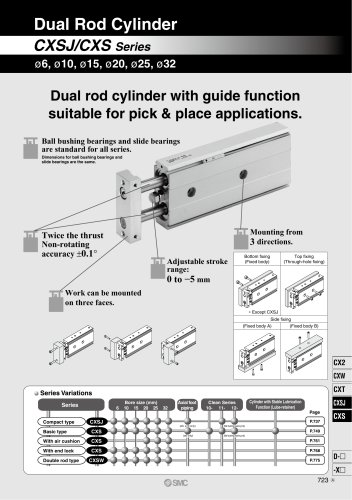 CXSJ
CXSJ60 Pages
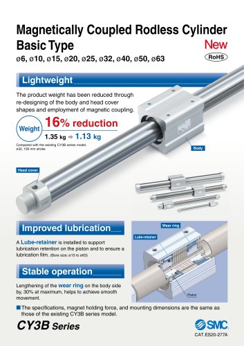 CY3B
CY3B17 Pages
 Aluminum High Vacuum Angle Valve
26 Pages
 AP Ultra High Purity
25 Pages
 IFW5 series
5 Pages
 Air Management System
64 Pages
 25A-ZSE20(F)/ISE20 Series
12 Pages
 ASG
ASG4 Pages
 IDG
IDG49 Pages
 CXSJ_M
2 Pages
 JLV20/30
8 Pages
 Series NCQ2/CQ2
252 Pages
 AC Series - Modular F.R.L. Units
70 Pages
 KQG2
KQG218 Pages
 IDF*E
IDF*E48 Pages
 AC10-A to AC40-A
82 Pages
 VQZ115, 100 Series
41 Pages
 SYJ300
60 Pages
 3000 Series
272 Pages
 MTS8
MTS823 Pages
 CXS-A
CXS-A60 Pages
 CXSL
CXSL60 Pages
 MXQR
MXQR36 Pages
 NC(D)Q2-Z
252 Pages
 LEY series
88 Pages
 MXH series
18 Pages
 KQ2
KQ2214 Pages
 Modular F.R.L. Units
108 Pages
 MXQ series
198 Pages
 Fieldbus System
92 Pages
 Fluoropolymer Piping Equipment
82 Pages
 Digital Flow Switch
24 Pages
 Vacuum Pad with Ejector
8 Pages
 Intrinsically safe Valve
43 Pages
 CQ2 series
25 Pages
 IDH, Thermo-dryer
12 Pages
 ISG
ISG10 Pages
 ISE3
ISE38 Pages
 ISE2
ISE27 Pages
 ISE1
ISE15 Pages
 ISA
ISA59 Pages
 IS3000
2 Pages
 IS10/10M/10E
4 Pages
 PSE series
44 Pages
 ISE70/75/75H
10 Pages
 ISE80
ISE8017 Pages
 ISE40A
29 Pages
 HED series
16 Pages
 HEC series
32 Pages
 HEB series
9 Pages
 HRG series
85 Pages
 HRZ series
52 Pages
 HRW series
28 Pages
 LQ series
35 Pages
 LVQ series catalog
75 Pages
 PA series
37 Pages
 EX600, Analog Input/Output Unit
59 Pages
 LER series
62 Pages
 LEJ series
58 Pages
 ISE/ZSE30A series
18 Pages
 LAT3 series
24 Pages
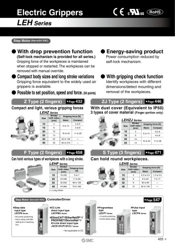
 LEH series
103 Pages
 CQS series
59 Pages
 CH series
175 Pages
 ARX series
12 Pages
 HRS series
47 Pages
 LES
LES59 Pages
 MHS
MHS74 Pages
 MHY
MHY27 Pages
 MHC
MHC27 Pages
 MHR
MHR30 Pages
 MHZ series
78 Pages
 MSQ
MSQ37 Pages
 MGP
MGP127 Pages
 MXS
MXS38 Pages
 NRB
NRB10 Pages
 MXW
MXW22 Pages
 MHT
MHT11 Pages
 MY3
MY354 Pages
 CQM
CQM15 Pages
 NCA1
NCA163 Pages
 CM2
CM2152 Pages
 NCM
NCM91 Pages
 NCG
NCG96 Pages
 NCRA1
NCRA15 Pages
 CS2
CS232 Pages
 T/TIA
T/TIA1 Page
 KR
KR7 Pages
 KF
KF16 Pages
 KQ
KQ80 Pages
 AFF
AFF80 Pages
 AMG
AMG80 Pages
 IDF
IDF16 Pages
 HAA
HAA3 Pages
 ZFA
ZFA14 Pages
 ZA
ZA13 Pages
 MHF
MHF32 Pages
 CRB
CRB44 Pages
 D
D117 Pages
 RB
RB23 Pages
 CEP
CEP44 Pages
 rsq
rsq30 Pages
 CLK
CLK51 Pages
 MK
MK20 Pages
 CLJ
CLJ65 Pages
 MGJ
MGJ7 Pages
 ZSE30A
17 Pages
 IDFB*E
89 Pages
 ISE10
ISE1016 Pages
 ITV1000/2000
50 Pages
 AW
AW27 Pages
 NVFM200
12 Pages
 NVM100
32 Pages
 LLA*A
LLA*A36 Pages
 VX3*
VX3*41 Pages
 SY3000
158 Pages
 CH(D)2
175 Pages
 M(D)SUB
31 Pages


Archived catalogs
 Rodless cylinder
52 Pages
 ZSE1 series
12 Pages
 Rack and Pinion Rotary Actuators
37 Pages
 Special Fittings
14 Pages
 Toggle Grippers
16 Pages
 SX series
138 Pages
 ACG series
25 Pages
 C95 Pneumatic Cylinder
50 Pages
 Shock Absorber
16 Pages
 Silencer
4 Pages
 Air Filter Catalog
18 Pages
 heavy Duty Actuators
88 Pages
 Self-seal Fittings Catalog
13 Pages
 Connectors Catalog
53 Pages

