- Catalogs
- SMC Corporation of America
- Toggle Grippers
- Products
- Catalogs
- News & Trends
- Exhibitions
Toggle Grippers

Toggle Grippers
The document provides comprehensive technical specifications and guidelines for the Series MHT2 Angular Style Air Gripper, Toggle Type. It covers ordering information, specifications, dimensions, component parts, safety instructions, and maintenance guidelines.
The MHT2 series air grippers are available in sizes 32, 40, 50, and 63 mm, featuring double-acting action suitable for heavy workpieces. The toggle mechanism ensures secure gripping even with pressure drops. Operating pressure ranges from 0.1 to 0.6 MPa, with an ambient and fluid temperature range of 5 to 60°C. No lubrication is required.
Details on ordering grippers include specifying bore size, action type, and the number of auto switches. Auto switches, available as reed or solid-state, can be ordered separately with specific electrical configurations.
Dimensions for models MHT2-32D, MHT2-40D, MHT2-50D, and MHT2-63D are detailed, including mounting thread specifications and finger angles. Information on mounting threads and ports for finger operation is also provided.
The gripper is made from materials like aluminum alloy, carbon steel, and stainless steel, with components such as side plates, fingers, and cylinders treated for durability.
Instructions for installing auto switches emphasize proper positioning and securing to ensure effective operation and safety.
Safety guidelines prevent hazards and equipment damage, stressing compatibility checks, trained personnel operation, and special considerations for applications like atomic energy or medical equipment.
Users should periodically check workpiece stability and use shims for adjustments. Guidelines for safe gripping condition verification are provided.
SMC products are designed for compressed air applications. Clean air is essential to prevent malfunction, and consultation with SMC is recommended for non-standard applications.
Installation requires thorough manual reading, maintenance space, and adherence to torque specifications. Avoid corrosive environments and ensure qualified personnel handle pneumatic systems.
Debris removal from piping is crucial before installation. Use air dryers or aftercoolers to prevent condensate-related malfunctions.
SMC products comply with ISO 9001 and ISO 14001 standards, CE mark, and CSA and UL standards, ensuring quality and safety.
SMC offers a global service network with contact information for regions including America, Europe, Oceania, and Asia, ensuring reliable support worldwide.
Catalog excerpts

Angular Style Air Gripper Toggle Type
Open the catalog to page 1
Angular Style Air Gripper Toggle Type heavy workpiece. holds workpiece even when pressure drops. Toggle type Bore size Auto switch Without auto switch (Built-in magnet) switch model, refer to the table below. Applicable Auto Switch/Refer to page 12-13-1 for further information on auto switches. *" O" marked solid state switches are produced upon receipt of order. • Refer to page 12-9-7 for details, because there are other auto switches available than above models. Made'0! Refer to page 12-13-25 for auto switch Switch Mounting Bracket Part No. Bore size • Switch mounting screw • Switch spacer...
Open the catalog to page 2
Angular Style Air Grlpper Toggle Type Series MHT2 Effective Gripping Force • Workpiece gripping point should be within the range indicated in the graph. ' Indication of effective gripping force The effective gripping force shown in the graphs to the right is expressed as F, which is the thrust of one finger, when both fingers and attachments are in full contact with the work- piece as shown in the figure below. I Be sure to read before handling. i I Safety Instructions and Common i I mentioned in this catalog, and refer i ■ Precautions on every series. : If a workpiece is to be gripped by using...
Open the catalog to page 3
Thread depth 10 (Both sides) Mounting thread Thread for mounting attachment Thread depth 10 (Both sides) Mounting thread Finger closing port Finger opening port Mounting thread Thread for mounting attachment
Open the catalog to page 4
Angular Style Air Gripper Toggle Type Series MHT2 Dimensions MHT2-50D Open 23° Closed –2° 8-M10 x 1.5 mounting thread Thread depth 12 (Both sides) 4-M8 x 1.25 thread depth 14 Mounting thread MHZ MHF MHL MHR MHK MHS Finger closing port Rc 1/4 Finger opening port Rc 1/4 MHC MHT MHY 4-M10 x 5 bottom hole dia. 8.6 Thread for mounting attachment 4-M10 x 1.5 thread depth 12 Mounting thread MHW MRHQ MHT2-63D Misc. D8-M12 x 1.75 mounting thread Thread depth 17 (Both sides) 20- Open 23° Closed –2° 4-M10 x 1.5 thread depth 18 Mounting thread Finger closing port Rc 1/4 Finger opening port Rc 1/4 4-M12 x...
Open the catalog to page 5
Replacement Parts Component Parts = For finger assembly, lever assembly, order 2 pieces per one unit. Attachment Design Use shims for fine adjustment of the attachment.
Open the catalog to page 6
Angular Style Air Gripper Toggle Type Series MHT2 Mounting of Auto Switch Auto Switch Hysteresis Rail mounting type Switch operating position (ON) Switch reset position (OFF) Direct mounting type D-A7, D-A8: Rail mounting type D-M9DV: Direct mounting type are shown above. Refer to page 12-13-1 for further information on other auto * For details, refer to Best Pneumatics Vol. 7/8/9/10, because there are other types of normally closed (NC = b contact) solid state switches.
Open the catalog to page 7
Auto Switch Installation Example Various auto switch applications are possible through different combinations of auto switch quantities and detecting positions. 1) Detection when Gripping Exterior of Workpiece Detection example reset position 2. Confirmation of workpiece held 3. Confirmation of workpiece released fingers fully fingers fully auto switch Switch turned on when fingers return. Switch turned on when gripping a When a workpiece is held (Normal operation): Switch to turn OFF (Light not illuminating) When a workpiece is not held (Abnormal operation) Switch to turn ON (Light illuminating)...
Open the catalog to page 8
Auto Switch Various auto switch applications are possible through different combinations of auto switch quantities and detecting positions. 2) Detection when Gripping Interior of Workpiece Detection example 1. Confirmation of fingers in reset 2. Confirmation of workpiece held 3. Confirmation of workpiece released fingers fully auto switch Switch turned ON when fingers return. Switch turned ON when gripping a When a workpiece is held (Normal operation): Switch to turn OFF (Light not illuminating) When a workpiece is not held (Abnormal operation) Switch to turn ON (Light illuminating) auto switch...
Open the catalog to page 9
Safety Instructions These safety instructions are intended to prevent a hazardous situation and/or equipment damage. These instructions indicate the level of potential hazard by labels of "Caution", "Warning" or "Danger". To ensure safety, be sure to observe ISO 4414 Note 1), JIS B 8370 Note 2) and other safety practices. Caution : Operator error could result in injury or equipment damage. Warning : Operator error could result in serious injury or loss of life. Danger : In extreme conditions, there is a possible result of serious injury or loss of life. Note 1) ISO 4414: Pneumatic fluid power--General...
Open the catalog to page 10
Common Precautions Be sure to read before handling. For detailed precautions on every series, refer to main text. Products represented in this catalog are designed for use in compressed air applications only (including vacuum), unless otherwise indicated. Do not use the product outside their design parameters. Please contact SMC when using the products in applications other than compressed air (including vacuum). Install the products and operate them only after reading the instruction manual carefully and understanding its contents. Also keep the manual where it can be referred to as 2. Securing...
Open the catalog to page 11
Quality Assurance Information Reliable quality of products in the global market To enable our customers throughout the world to use our products with even greater confidence, SMC has obtained certification for international structure for quality assurance and products pursue to meet its customers' expectations while also considering company's contribution in Quality management system This is an international standard for quality control and quality assurance. SMC has obtained a large number of certifications in Japan and overseas, providing assurance to our customers throughout SMC's quality...
Open the catalog to page 12
SMC Product Conforming to Inter SMC products complying with EN/ISO, CSA/UL standards are supporting CE Mark The CE mark indicates that machines and components meet essential requirements of all the EC Directives applied. It has been obligatory to apply CE marks indicating conformity with EC Directives when machines and components are exported to the member Nations of the EU. Once “A manufacturer himself” declares a product to be safe by means of CE marking (declaration of conformity by manufacturer), free distribution inside the member Nations of the EU is permissible. í CE Mark SMC provides...
Open the catalog to page 13All SMC Corporation of America catalogs and technical brochures
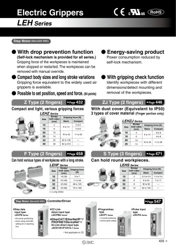 LEHZ
LEHZ67 Pages
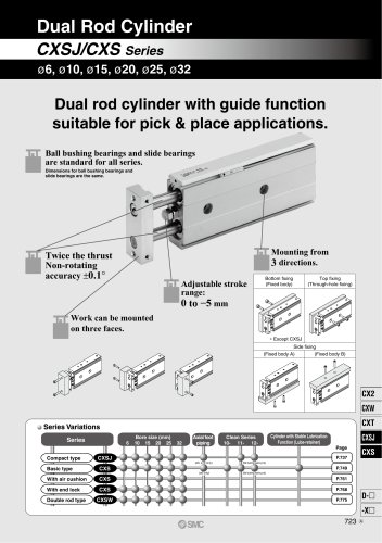 CXSJ
CXSJ60 Pages
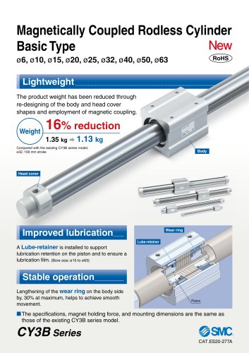 CY3B
CY3B17 Pages
 Aluminum High Vacuum Angle Valve
26 Pages
 AP Ultra High Purity
25 Pages
 IFW5 series
5 Pages
 Air Management System
64 Pages
 25A-ZSE20(F)/ISE20 Series
12 Pages
 ASG
ASG4 Pages
 IDG
IDG49 Pages
 CXSJ_M
2 Pages
 JLV20/30
8 Pages
 Series NCQ2/CQ2
252 Pages
 AC Series - Modular F.R.L. Units
70 Pages
 KQG2
KQG218 Pages
 IDF*E
IDF*E48 Pages
 AC10-A to AC40-A
82 Pages
 VQZ115, 100 Series
41 Pages
 SYJ300
60 Pages
 3000 Series
272 Pages
 MTS8
MTS823 Pages
 CXS-A
CXS-A60 Pages
 CXSL
CXSL60 Pages
 MXQR
MXQR36 Pages
 NC(D)Q2-Z
252 Pages
 LEY series
88 Pages
 MXH series
18 Pages
 KQ2
KQ2214 Pages
 Modular F.R.L. Units
108 Pages
 MXQ series
198 Pages
 Fieldbus System
92 Pages
 Fluoropolymer Piping Equipment
82 Pages
 Digital Flow Switch
24 Pages
 Vacuum Pad with Ejector
8 Pages
 Intrinsically safe Valve
43 Pages
 CQ2 series
25 Pages
 IDH, Thermo-dryer
12 Pages
 ISG
ISG10 Pages
 ISE3
ISE38 Pages
 ISE2
ISE27 Pages
 ISE1
ISE15 Pages
 ISA
ISA59 Pages
 IS3000
2 Pages
 IS10/10M/10E
4 Pages
 PSE series
44 Pages
 ISE70/75/75H
10 Pages
 ISE80
ISE8017 Pages
 ISE40A
29 Pages
 HED series
16 Pages
 HEC series
32 Pages
 HEB series
9 Pages
 HRG series
85 Pages
 HRZ series
52 Pages
 HRW series
28 Pages
 LQ series
35 Pages
 LVQ series catalog
75 Pages
 PA series
37 Pages
 EX600, Analog Input/Output Unit
59 Pages
 LER series
62 Pages
 LEJ series
58 Pages
 ISE/ZSE30A series
18 Pages
 LAT3 series
24 Pages
 LEH series
103 Pages
 CQS series
59 Pages
 CH series
175 Pages
 ARX series
12 Pages
 HRS series
47 Pages
 LES
LES59 Pages
 MHS
MHS74 Pages
 MHY
MHY27 Pages
 MHC
MHC27 Pages
 MHR
MHR30 Pages
 MHZ series
78 Pages
 MSQ
MSQ37 Pages
 MGP
MGP127 Pages
 MXS
MXS38 Pages
 NRB
NRB10 Pages
 MXW
MXW22 Pages
 MHT
MHT11 Pages
 MY3
MY354 Pages
 CQM
CQM15 Pages
 NCA1
NCA163 Pages
 CM2
CM2152 Pages
 NCM
NCM91 Pages
 NCG
NCG96 Pages
 NCRA1
NCRA15 Pages
 CS2
CS232 Pages
 T/TIA
T/TIA1 Page
 KR
KR7 Pages
 KF
KF16 Pages
 KQ
KQ80 Pages
 AFF
AFF80 Pages
 AMG
AMG80 Pages
 IDF
IDF16 Pages
 HAA
HAA3 Pages
 ZFA
ZFA14 Pages
 ZA
ZA13 Pages
 MHF
MHF32 Pages
 CRB
CRB44 Pages
 D
D117 Pages
 RB
RB23 Pages
 CEP
CEP44 Pages
 rsq
rsq30 Pages
 CLK
CLK51 Pages
 MK
MK20 Pages
 CLJ
CLJ65 Pages
 MGJ
MGJ7 Pages
 ZSE30A
17 Pages
 IDFB*E
89 Pages
 ISE10
ISE1016 Pages
 ITV1000/2000
50 Pages
 AW
AW27 Pages
 NVFM200
12 Pages
 NVM100
32 Pages
 LLA*A
LLA*A36 Pages
 VX3*
VX3*41 Pages
 SY3000
158 Pages
 CH(D)2
175 Pages
 M(D)SUB
31 Pages


Archived catalogs
 Rodless cylinder
52 Pages
 ZSE1 series
12 Pages
 Rack and Pinion Rotary Actuators
37 Pages
 Special Fittings
14 Pages
 SX series
138 Pages
 ACG series
25 Pages
 C95 Pneumatic Cylinder
50 Pages
 Shock Absorber
16 Pages
 Silencer
4 Pages
 VV061 series
11 Pages
 Air Filter Catalog
18 Pages
 heavy Duty Actuators
88 Pages
 Self-seal Fittings Catalog
13 Pages
 Connectors Catalog
53 Pages

