SY3000
1 /158Pages

SY3000
1 /158Pages
Catalog excerpts

5 Port Solenoid Valve 10 mm width can drive a 050 cylinder. 15 mm width can drive a 063 cylinder. *Values based on comparison with the conventional SMC model. Refer to page 4 for common conditions. Thanks to the flow increase, valve size can be reduced. Saves energy and space. • Added the EX260 Integrated-type (For Output) Serial Transmission System. • Added EtherNet/IP™, EtherCATto the EX600 Integrated-type (For Input/Output) Serial Transmission System (Fieldbus System). • Additional Options: Interface regulator assembly Individual SUP block assembly Individual EXH block assembly Dual flow fitting Name plate for manifolds Power Consumption [Electrical power waveform with power saving circuit] With power saving circuit Power consumption is reduced by power saving circuit. Power consumption is decreased by approx. 1/3 by reducing the wattage required to hold the valve in an energized state. (Effective energizing time is over 67 ms at 24 VDC.) Refer to the electrical power waveform as shown on the right. With power saving circuit The value In ( ) are for the quick response and high pressure types. Rubber seal Metal seal (Rubber seal) (Metal seal) * According to SMC life test conditions
Open the catalog to page 1
5 Port Solenoid Valve senes SY3000/5000 Plug-in metal base [IP40] Plug-in connector connecting base [IP67Note)] • Connector type manifold Space saving / Improved operability " $t,lJ Note) Refer to page 6 for 5 Connector type manifold Wiring, piping and operation are Multiple layer type is available as an option. This saves space in the lateral direction. Bottom ported is prepared. Space saving Bottom ported reduces the footprint. SUP stop valve spacer with residual pressure release valve Individual SUP/EXH spacer Direction, size and type of the piping can be changed. One-touch fitting Port block...
Open the catalog to page 2
Double check spacer with residual pressure release valve Long time of intermediate stop and position holding are possible. [Intermediate stop] [Drop prevention] Button for manual release of residual pressure Double check spacer assembly Double check spacer assembly cylinder side. Exhaust center SUP stop valve spacer with residual pressure release valve Air supply to each valve can be stopped individually. The valve and cylinder can be replaced without stopping other devices and equipment. Button for manual release cylinder side. spacer assembly 2-position single valve example Applicable to various...
Open the catalog to page 3
Manifold Variations Manifold Variations Serial transmission Standard O Option ▲ Made-to-Order (Refer to page 14.) Plug-in Metal Base D-sub connector Flat ribbon cable, Serial transmission: Plug-in Connector Connecting Base D-sub connector Plug-in Connector Connecting Base Circular connector Serial transmission: Serial transmission: Serial transmission:
Open the catalog to page 4
Manifold Options (Pages 141 to 148) One-touch fittings Valve Options ): Elbow piping may specify size only in millimeters, depending on the port size. Refer to How to Order Manifold for details. 2): Refer to Manifold Specifications for details on IP67. Flat ribbon cable, Lead wire One-touch fittings Serial transmission: Serial transmission: Serial transmission: Straight piping Elbow piping
Open the catalog to page 5
Manifold Variations P. 1 Optimum Actuation Size Chart of Air Cylinder P. 4 Plug-in Metal Base P. 5 Plug-in Connector Connecting Base P. 6 Valve Specifications (Specifications, Response Time, Weight) P. 8 Valve Construction P. 10 Valve Replacement Parts P. 13 Made-to-Order for Valve P. 14 Plug-in Metal Base Type 50/ Side ported Type 51/ Bottom ported Type 52/ Top ported Type 50/Side Ported, Type 51/Bottom Ported, Type 52/Top Ported P. 15 D-sub Connector, Flat Ribbon Cable, PC Wiring System [IP40] Type 50/Side Ported Type 51/Bottom Ported Flat ribbon cable P. 15 Type 52/Top Ported D-sub connector...
Open the catalog to page 6
Optimum Actuation Size Chart of Air Cylinder [Common conditions] • Connector type manifold Side and bottom ported type Please check the actual conditions with SMC Sizing Program.
Open the catalog to page 7
Plug-in Metal Base Manifold Specifications Manifold Flow-rate Characteristics /Manifold Weight Valve Seal Type: Rubber Seal_ Valve Seal Type: Metal Seal * Calculation of effective area S and sonic conductance C: S = 5.0 x C Note 1) The value is for manifold base with 5 stations and individually operated 2-position type. Note 2) Weight: W is the value for the D-sub connector manifold. To obtain the weight with valves attached, add the valve weights given on page 9 for the appropriate number of stations.
Open the catalog to page 8
Plug-in Connector Connecting Base Manifold Specifications Manifold Flow-rate Characteristics /Manifold Weight Valve Seal Type: Rubber Seal Valve Seal Type: Metal Seal * Calculation of effective area S and sonic conductance C: S = 5.0 x C Note 1) The value is for manifold base with 5 stations and individually operated 2-position type. Note 2) Weight: W is the value of the internal pilot, and D-sub connector manifold with one-touch fitting straight piping type. To obtain the weight with valves attached, add the valve weights given on page 9 for the appropriate number of stations.
Open the catalog to page 9
Connector Wiring Layout For both serial and parallel wiring, additional valves are sequentially assigned pins on the connector. This makes it completely unnecessary to disassemble the connector unit. ■ Single solenoid valve is installed to all double wiring, (in case of all double wiring) (Manifold specification sheet is not necessary.) Solenoid Connector side Station 3 (Double wiring) Station 1 Single/double wiring are mixed. (Manifold specification sheet is necessary.) Double solenoid Single solenoid Double solenoid Connector side Note) These diagrams are for the purpose of explanation, and...
Open the catalog to page 10
Valve Specifications Note 1) Use below 5 Hz for with power saving circuit. Note 2) Impact resistance: No malfunction occurred when it is tested in the axial direction and at the right angles to the main valve and armature in both energized and de-energized states every once for each condition. (Values at the initial period) Vibration resistance: No malfunction occurred in a one-sweep test between 45 and 2000 Hz. Test was performed at both energized and de-energized states in the axial direction and at the right angles to the main valve and armature. (Values at the initial period) Note 3) Due...
Open the catalog to page 11All SMC Corporation of America catalogs and technical brochures
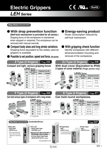 LEHZ
LEHZ67 Pages
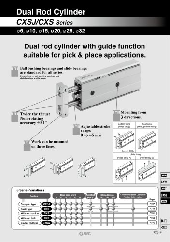 CXSJ
CXSJ60 Pages
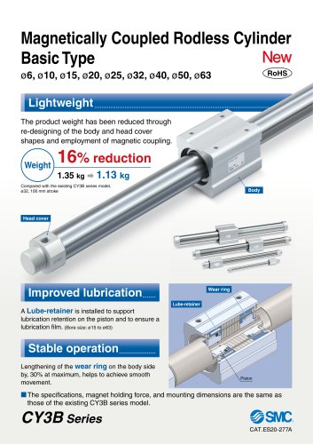 CY3B
CY3B17 Pages
 Aluminum High Vacuum Angle Valve
26 Pages
 AP Ultra High Purity
25 Pages
 IFW5 series
5 Pages
 Air Management System
64 Pages
 25A-ZSE20(F)/ISE20 Series
12 Pages
 ASG
ASG4 Pages
 IDG
IDG49 Pages
 CXSJ_M
2 Pages
 JLV20/30
8 Pages
 Series NCQ2/CQ2
252 Pages
 AC Series - Modular F.R.L. Units
70 Pages
 KQG2
KQG218 Pages
 IDF*E
IDF*E48 Pages
 AC10-A to AC40-A
82 Pages
 VQZ115, 100 Series
41 Pages
 SYJ300
60 Pages
 3000 Series
272 Pages
 MTS8
MTS823 Pages
 CXS-A
CXS-A60 Pages
 CXSL
CXSL60 Pages
 MXQR
MXQR36 Pages
 NC(D)Q2-Z
252 Pages
 LEY series
88 Pages
 MXH series
18 Pages
 KQ2
KQ2214 Pages
 Modular F.R.L. Units
108 Pages
 MXQ series
198 Pages
 Fieldbus System
92 Pages
 Fluoropolymer Piping Equipment
82 Pages
 Digital Flow Switch
24 Pages
 Vacuum Pad with Ejector
8 Pages
 Intrinsically safe Valve
43 Pages
 CQ2 series
25 Pages
 IDH, Thermo-dryer
12 Pages
 ISG
ISG10 Pages
 ISE3
ISE38 Pages
 ISE2
ISE27 Pages
 ISE1
ISE15 Pages
 ISA
ISA59 Pages
 IS3000
2 Pages
 IS10/10M/10E
4 Pages
 PSE series
44 Pages
 ISE70/75/75H
10 Pages
 ISE80
ISE8017 Pages
 ISE40A
29 Pages
 HED series
16 Pages
 HEC series
32 Pages
 HEB series
9 Pages
 HRG series
85 Pages
 HRZ series
52 Pages
 HRW series
28 Pages
 LQ series
35 Pages
 LVQ series catalog
75 Pages
 PA series
37 Pages
 EX600, Analog Input/Output Unit
59 Pages
 LER series
62 Pages
 LEJ series
58 Pages
 ISE/ZSE30A series
18 Pages
 LAT3 series
24 Pages
 LEH series
103 Pages
 CQS series
59 Pages
 CH series
175 Pages
 ARX series
12 Pages
 HRS series
47 Pages
 LES
LES59 Pages
 MHS
MHS74 Pages
 MHY
MHY27 Pages
 MHC
MHC27 Pages
 MHR
MHR30 Pages
 MHZ series
78 Pages
 MSQ
MSQ37 Pages
 MGP
MGP127 Pages
 MXS
MXS38 Pages
 NRB
NRB10 Pages
 MXW
MXW22 Pages
 MHT
MHT11 Pages
 MY3
MY354 Pages
 CQM
CQM15 Pages
 NCA1
NCA163 Pages
 CM2
CM2152 Pages
 NCM
NCM91 Pages
 NCG
NCG96 Pages
 NCRA1
NCRA15 Pages
 CS2
CS232 Pages
 T/TIA
T/TIA1 Page
 KR
KR7 Pages
 KF
KF16 Pages
 KQ
KQ80 Pages
 AFF
AFF80 Pages
 AMG
AMG80 Pages
 IDF
IDF16 Pages
 HAA
HAA3 Pages
 ZFA
ZFA14 Pages
 ZA
ZA13 Pages
 MHF
MHF32 Pages
 CRB
CRB44 Pages
 D
D117 Pages
 RB
RB23 Pages
 CEP
CEP44 Pages
 rsq
rsq30 Pages
 CLK
CLK51 Pages
 MK
MK20 Pages
 CLJ
CLJ65 Pages
 MGJ
MGJ7 Pages
 ZSE30A
17 Pages
 IDFB*E
89 Pages
 ISE10
ISE1016 Pages
 ITV1000/2000
50 Pages
 AW
AW27 Pages
 NVFM200
12 Pages
 NVM100
32 Pages
 LLA*A
LLA*A36 Pages
 VX3*
VX3*41 Pages
 CH(D)2
175 Pages
 M(D)SUB
31 Pages


Archived catalogs
 Rodless cylinder
52 Pages
 ZSE1 series
12 Pages
 Rack and Pinion Rotary Actuators
37 Pages
 Special Fittings
14 Pages
 Toggle Grippers
16 Pages
 SX series
138 Pages
 ACG series
25 Pages
 C95 Pneumatic Cylinder
50 Pages
 Shock Absorber
16 Pages
 Silencer
4 Pages
 VV061 series
11 Pages
 Air Filter Catalog
18 Pages
 heavy Duty Actuators
88 Pages
 Self-seal Fittings Catalog
13 Pages
 Connectors Catalog
53 Pages

