
- Catalogs
- SMC Corporation of America
- Rodless cylinder


Rodless cylinder

Rodless cylinder
Catalog excerpts

MY3A3B.qxd 06.2.17 9:13 AM Page 1 CAT.ES20-165 B Mechanically Jointed Rodless Cylinders Basic short type (Rubber bumper) Series MY3A Basic standard type (Air cushion) Series MY3B Slide bearing type (Air cushion) Series MY3M Series Variations Series Type MY3A Basic short type MY3B Basic standard type Piping type MY3M Slide bearing type Bore size (mm) 16 25 40 63 Rubber bumper Air cushion Stroke adjusting unit Side support Floating bracket Made to Order Long stroke (-XB11) Centralized piping Helical insert threads (-X168) Standard piping Holder mounting bracket Note) (-X416, X417) Copper-free (20-) Note) Except the MY3A
Open the catalog to page 1
High functionality with reduced height and length Mechanically Jointed Rodless Cylinders Basic short type (Rubber bumper) Basic standard type -oading Capacity Slide bearing type Work pieces can be loaded directly on the work table Overall length (Z) reduced by 140 mm at the maximum Height (H) reduced by 36% at the maximum MY3A (with rubber bumper) Overall length (Z + Stroke) Weight reduced by 53% at the maximum
Open the catalog to page 2
MY3A3B.qxd 06.2.17 9:13 AM Page 3 Floating Bracket Easy connection with external guide. Vertical and lateral mounting is possible. (Page 16) Stroke Adjusting Unit (MY3A/3B) (MY3B/3M) Side Support The cylinder tube can be fixed from the upper or lower side. (Page 15, 27) Auto Switch Centralized Piping Can be mounted on both sides from the front direction. Integrated piping in the head cover is possible. (Refer to the back of page 6.) Positioning cushion mechanism The uniquely designed piston shape enables reduction of the height and length as well as practical arrangement of the common piping...
Open the catalog to page 3
The following are steps for selecting the MY3 series which is best suited to your application. Guideline for Tentative Model Selection © Most suitable O Suitable A Usable X Not recommended Note) The table accuracy means the amount of table deflection when a moment is applied. Selection Flow Chart When an external guide is used, the selection confirmation of the guide capacity should follow the selection procedure The MY3 series allow direct load application within the allowable range for the built-in guide. The payload in this case will vary depending on the driving speed and the mounting orientation...
Open the catalog to page 4
Model Selection Series MY3 Stroke positioning Shock absorber Maximum operating speed Rubber bumper Direct loaded Stroke adjusting unit Shock absorber External stopper External shock Rubber bumper Stroke adjusting unit Shock absorber External stopper External shock Note 1) The shock absorber must meet the conditions mentioned on page 7. Note 2) As the external shock absorber, a unit with appropriate capacity and features should be installed close to the load center of gravity. Note 3) Use the stroke adjusting unit of the MY3B series with an external guide. Note 4) Shown below are the details of...
Open the catalog to page 5
Types of Moment Applied to Rodless Cylinders Multiple moments may be generated depending on the mounting orientation, load and position of the center of gravity. Load Weight and Static Moment Note) ITU is a mass movable by thrust. Use 0.3 to 0.7 times the thrust (differs depending on the operating speed) as a guide for actual use. Dynamic Moment Note) Regardless of the mounting orientation, dynamic moment is calculated with the formulae above. Calculation of Guide Load Factor 1. Maximum load weight (1), static moment (2), and dynamic moment (3) (at the time of impact with stopper) must be examined...
Open the catalog to page 6
MY3A3B.qxd 06.2.17 9:13 AM Page 7 Series MY3 Model Selection 2 The following are steps for selecting the MY3 series which is best suited to your application. Calculation of Guide Load Factor 1 Operating Conditions Cylinder • • • • • • • • • • • • • • • • • • • • • • • • • • • • • • • • • • • • • • Average operating speed υa • • • • • • • • • • Mounting direction • • • • • • • • • • • • • • • • • • • • • • • Cushion • • • • • • • • • • • • • • • • • • • • • • • • • • • • • • • • • • • • • • Mounting Direction MY3A25-500 300 mm/s Horizontal mounting Rubber bumper (δ = 4/100) 1. Horizontal z mounting...
Open the catalog to page 7
Calculation of Guide Load Factor A] Calculation of Load Factor for Dynamic Moment- Equivalent load FE at impact MIE max (from © of graph MY3A/M1 where 1.4Da = 420 mm/s) = 2.85 (N«m) Load factor CM = MIE/MIE max = 0.88/2.85 = 0.31 M3E max (from © of graph MY3A/M3 where 1.4Da = 420 mm/s) = 0.95 (N«m) 5j Sum and Examination of Guide Load Factors- The above calculation is within the allowable value, and therefore the selected model can be used. Select a shock absorber separately. In an actual calculation, when the sum of guide load factors Ea in the formula above is more than 1, consider decreasing...
Open the catalog to page 8
MY3A3B.qxd 06.2.17 9:13 AM Page 10 Series MY3A/3B Model Selection The following are steps for selecting the MY3 series which is best suited to your application. Calculation of Guide Load Factor 1 Operating Conditions Cylinder • • • • • • • • • • • • • • • • • • • • • • • • • • • • • • • • • • • • • • Average operating speed υa • • • • • • • • • • Mounting direction • • • • • • • • • • • • • • • • • • • • • • • Cushion • • • • • • • • • • • • • • • • • • • • • • • • • • • • • • • • • • • • • • Mounting Direction MY3A25-500 300 mm/s Horizontal mounting Rubber bumper (δ = 4/100) 1. Horizontal z...
Open the catalog to page 10All SMC Corporation of America catalogs and technical brochures
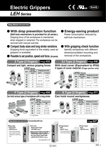 LEHZ
LEHZ67 Pages
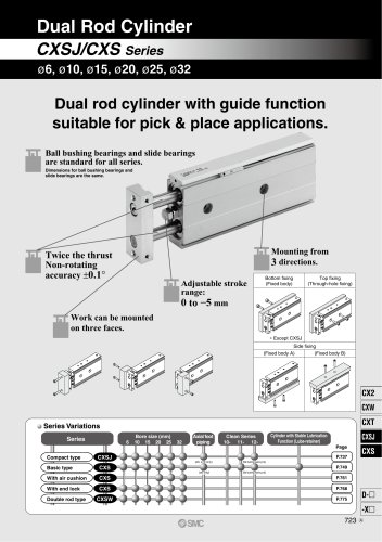 CXSJ
CXSJ60 Pages
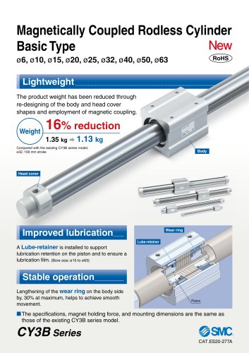 CY3B
CY3B17 Pages
 Aluminum High Vacuum Angle Valve
26 Pages
 AP Ultra High Purity
25 Pages
 IFW5 series
5 Pages
 Air Management System
64 Pages
 25A-ZSE20(F)/ISE20 Series
12 Pages
 ASG
ASG4 Pages
 IDG
IDG49 Pages
 CXSJ_M
2 Pages
 JLV20/30
8 Pages
 Series NCQ2/CQ2
252 Pages
 AC Series - Modular F.R.L. Units
70 Pages
 KQG2
KQG218 Pages
 IDF*E
IDF*E48 Pages
 AC10-A to AC40-A
82 Pages
 VQZ115, 100 Series
41 Pages
 SYJ300
60 Pages
 3000 Series
272 Pages
 MTS8
MTS823 Pages
 CXS-A
CXS-A60 Pages
 CXSL
CXSL60 Pages
 MXQR
MXQR36 Pages
 NC(D)Q2-Z
252 Pages
 LEY series
88 Pages
 MXH series
18 Pages
 KQ2
KQ2214 Pages
 Modular F.R.L. Units
108 Pages
 MXQ series
198 Pages
 Fieldbus System
92 Pages
 Fluoropolymer Piping Equipment
82 Pages
 Digital Flow Switch
24 Pages
 Vacuum Pad with Ejector
8 Pages
 Intrinsically safe Valve
43 Pages
 CQ2 series
25 Pages
 IDH, Thermo-dryer
12 Pages
 ISG
ISG10 Pages
 ISE3
ISE38 Pages
 ISE2
ISE27 Pages
 ISE1
ISE15 Pages
 ISA
ISA59 Pages
 IS3000
2 Pages
 IS10/10M/10E
4 Pages
 PSE series
44 Pages
 ISE70/75/75H
10 Pages
 ISE80
ISE8017 Pages
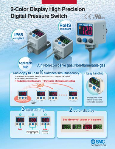 ISE40A
29 Pages
 HED series
16 Pages
 HEC series
32 Pages
 HEB series
9 Pages
 HRG series
85 Pages
 HRZ series
52 Pages
 HRW series
28 Pages
 LQ series
35 Pages
 LVQ series catalog
75 Pages
 PA series
37 Pages
 EX600, Analog Input/Output Unit
59 Pages
 LER series
62 Pages
 LEJ series
58 Pages
 ISE/ZSE30A series
18 Pages
 LAT3 series
24 Pages
 LEH series
103 Pages
 CQS series
59 Pages
 CH series
175 Pages
 ARX series
12 Pages
 HRS series
47 Pages
 LES
LES59 Pages
 MHS
MHS74 Pages
 MHY
MHY27 Pages
 MHC
MHC27 Pages
 MHR
MHR30 Pages
 MHZ series
78 Pages
 MSQ
MSQ37 Pages
 MGP
MGP127 Pages
 MXS
MXS38 Pages
 NRB
NRB10 Pages
 MXW
MXW22 Pages
 MHT
MHT11 Pages
 MY3
MY354 Pages
 CQM
CQM15 Pages
 NCA1
NCA163 Pages
 CM2
CM2152 Pages
 NCM
NCM91 Pages
 NCG
NCG96 Pages
 NCRA1
NCRA15 Pages
 CS2
CS232 Pages
 T/TIA
T/TIA1 Page
 KR
KR7 Pages
 KF
KF16 Pages
 KQ
KQ80 Pages
 AFF
AFF80 Pages
 AMG
AMG80 Pages
 IDF
IDF16 Pages
 HAA
HAA3 Pages
 ZFA
ZFA14 Pages
 ZA
ZA13 Pages
 MHF
MHF32 Pages
 CRB
CRB44 Pages
 D
D117 Pages
 RB
RB23 Pages
 CEP
CEP44 Pages
 rsq
rsq30 Pages
 CLK
CLK51 Pages
 MK
MK20 Pages
 CLJ
CLJ65 Pages
 MGJ
MGJ7 Pages
 ZSE30A
17 Pages
 IDFB*E
89 Pages
 ISE10
ISE1016 Pages
 ITV1000/2000
50 Pages
 AW
AW27 Pages
 NVFM200
12 Pages
 NVM100
32 Pages
 LLA*A
LLA*A36 Pages
 VX3*
VX3*41 Pages
 SY3000
158 Pages
 CH(D)2
175 Pages
 M(D)SUB
31 Pages


Archived catalogs
 ZSE1 series
12 Pages
 Rack and Pinion Rotary Actuators
37 Pages
 Special Fittings
14 Pages
 Toggle Grippers
16 Pages
 SX series
138 Pages
 ACG series
25 Pages
 C95 Pneumatic Cylinder
50 Pages
 Shock Absorber
16 Pages
 Silencer
4 Pages
 VV061 series
11 Pages
 Air Filter Catalog
18 Pages
 heavy Duty Actuators
88 Pages
 Self-seal Fittings Catalog
13 Pages
 Connectors Catalog
53 Pages

