- Catalogs
- SMC Corporation of America
- PA series
PA series
1 /37Pages

PA series
1 /37Pages
Catalog excerpts

Process Pump Series Series Compact, high capacity diaphragm pump for transfer and recovery of a wide variety of fluids Long service life, 2 to 5 times that of conventional pumps No sliding parts in wetted areas. Self-priming makes priming unnecessary Built-in pulsation attenuator Compact single acting Process pump Process pump Automatically operated type/Air operated type Automatically operated type Built-in solenoid valve type/Air operated type (Internal switching type) (Internal switching type) (External switching type) High abrasion resistance and low particle generation VQ Incorporates a new diaphragm material. Enlarged bore size and shortened stroke extend life. (Compared to series PA2000) Process pump (External switching type) (External switching type) A solenoid valve operated pump that fits in the palm of the hand Prevents spraying of discharge and foaming in tank Variations Series PA: Double Acting Pump LVN Discharge flow rate (l /min) Automatically operated type Air operated type Automatically operated type with built-in pulsation attenuator Material Body ADC12 (Aluminum) SCS14 (Stainless steel) ADC12 (Aluminum) SCS14 (Stainless steel) Series PB: Single Acting Pump PB1011 Built-in solenoid valve Application Example Transferring liquid by suction Automatically operated type Air operated type Compatible with a Control with external switching valve makes constant cycling possible wide variety of fluids Atomizing liquid Transferring liquid by pressure Stirring liquid • Prevents sticking of liquids
Open the catalog to page 1
Be sure to read before handling. Refer to pages 17-6-3 to 17-6-10 for Safety Instructions and Solenoid Valve Precautions. Caution on Design Warning 1. Confirm the fluid to be used. Be sure to confirm the specifications, as the fluids to be used differ depending on the product. When different fluids are used, characteristics change and this can cause faulty operation. 2. Fluid temperature Use each model within its respective fluid temperature range. 3. Fluid quality If fluid is used which contains foreign matter, troubles such as malfunction and seal failure may occur due to wearing of valve seats...
Open the catalog to page 2
Process Pump Precautions 2 Be sure to read before handling. Refer to pages 17-6-3 to 17-6-10 for Safety Instructions and Solenoid Valve Precautions. Selection 1. Confirm the specifications. Give careful consideration to operating conditions such as the application, fluid and environment, and use within the operating ranges specified in this catalog. 2. Type of fluid Operate only after confirming the materials and applicable fluids for each model to determine which fluids can be used. 3. Equipment selection When selecting equipment, make a selection from the latest catalog, staying within specified...
Open the catalog to page 3
Be sure to read before handling. Refer to pages 17-6-3 to 17-6-10 for Safety Instructions and Solenoid Valve Precautions. Operating Environment Warning 1. Do not use in the following environments, as this can cause failure. 1) Locations with an atmosphere of corrosive gases, organic solvents or chemical solutions, and where there may be contact with the same. 2) Locations where there is contact with sea spray, water or steam. 3) Locations where there is contact with direct sunlight. (Sunlight should be blocked to prevent deterioration of resin from ultra violet rays and over heating, etc.) 4)...
Open the catalog to page 4
Process Pump Precautions 4 Be sure to read before handling. Refer to pages 17-6-3 to 17-6-10 for Safety Instructions and Solenoid Valve Precautions. Maintenance Caution 6. Concerning the life span of diaphragm and the maintenance of consumable items. 1) Regular maintenance is required for Diaphragm, Check valve and Switching valve, etc. • If the diaphragm is not functioning, the operating fluid may flow to the pilot air side and at the same time the operating air may flow out to the liquid circuit. This makes it impossible to restart the operation. • Consider the pump operation (breathing, decline...
Open the catalog to page 5
Be sure to read before handling. Refer to pages 17-6-3 to 17-6-10 for Safety Instructions and Solenoid Valve Precautions. Fluid Compatibility Caution 1. Select models by choosing liquid contact materials suitable for the liquids to be transferred. • In liquid contact areas, aluminum is suitable for use with oils, and stainless steel is suitable for solvents and industrial water. • For the diaphragm material, nitrile rubber is suitable with inert liquids, and fluororesin is suitable with non-permeating liquids. • Use fluids which will not corrode the wetted parts materials. 2. Transfer examples...
Open the catalog to page 6
Process Pump Automatically Operated Type (Internal Switching Type) Body only With silencer ∗ Port size Material of body wetted areas 1 2 ADC12 (Aluminum) SCS14 (Stainless steel) Thread type Automatically operated type Specifications Model Main fluid suction discharge port FLUID OUT Port size Average discharge pressure Operating fluid temperature Ambient temperature Pilot air pressure Check valve Discharge rate Suction lifting range Pilot air supply/ exhaust port Body wetted areas Automatically operated type Automatically operated type (liquid inside pump) 0 to 60°C (No freezing) 0 to 60°C 0.2...
Open the catalog to page 8
Process Pump Automatically Operated Type Series Performance Curve: Automatically Operated Type Discharge rate (i/min) Selection from Flow Characteristic Graph (PA3000) Required specifications example: Find the pilot air pressure and pilot air consumption for a discharge rate of 6 £/m'm and a total lifting range of 25 m. <The transfer fluid is fresh water (viscosity 1 mPa-s, specific gravity 1.0). * If the discharge pressure is required instead of the total lifting height, a total lift of 10 m corresponds to discharge pressure of 0.1 MPa. Selection procedures: 1. First mark the intersection point...
Open the catalog to page 9
Working Principle: Automatically Operated Type Drive unit Control unit Switching valve Discharge port (FLUID OUT) Pump chamber A Check valve Pump chamber B Shaft Suction port (FLUID IN) Drive chamber B Diaphragm B Control unit 1. When air is supplied, it passes through the switching valve and enters drive chamber B. 2. Diaphragm B moves to the right, and at the same time diaphragm A also moves to the right pushing pilot valve A. 3. When pilot valve A is pushed, air acts upon the switching valve, drive chamber A switches to a supply state, and the air which was in drive chamber B is exhausted...
Open the catalog to page 10All SMC Corporation of America catalogs and technical brochures
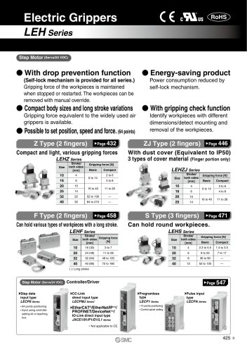 LEHZ
LEHZ67 Pages
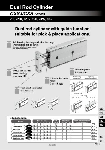 CXSJ
CXSJ60 Pages
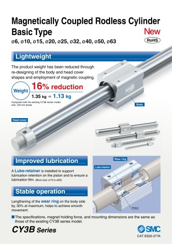 CY3B
CY3B17 Pages
 Aluminum High Vacuum Angle Valve
26 Pages
 AP Ultra High Purity
25 Pages
 IFW5 series
5 Pages
 Air Management System
64 Pages
 25A-ZSE20(F)/ISE20 Series
12 Pages
 ASG
ASG4 Pages
 IDG
IDG49 Pages
 CXSJ_M
2 Pages
 JLV20/30
8 Pages
 Series NCQ2/CQ2
252 Pages
 AC Series - Modular F.R.L. Units
70 Pages
 KQG2
KQG218 Pages
 IDF*E
IDF*E48 Pages
 AC10-A to AC40-A
82 Pages
 VQZ115, 100 Series
41 Pages
 SYJ300
60 Pages
 3000 Series
272 Pages
 MTS8
MTS823 Pages
 CXS-A
CXS-A60 Pages
 CXSL
CXSL60 Pages
 MXQR
MXQR36 Pages
 NC(D)Q2-Z
252 Pages
 LEY series
88 Pages
 MXH series
18 Pages
 KQ2
KQ2214 Pages
 Modular F.R.L. Units
108 Pages
 MXQ series
198 Pages
 Fieldbus System
92 Pages
 Fluoropolymer Piping Equipment
82 Pages
 Digital Flow Switch
24 Pages
 Vacuum Pad with Ejector
8 Pages
 Intrinsically safe Valve
43 Pages
 CQ2 series
25 Pages
 IDH, Thermo-dryer
12 Pages
 ISG
ISG10 Pages
 ISE3
ISE38 Pages
 ISE2
ISE27 Pages
 ISE1
ISE15 Pages
 ISA
ISA59 Pages
 IS3000
2 Pages
 IS10/10M/10E
4 Pages
 PSE series
44 Pages
 ISE70/75/75H
10 Pages
 ISE80
ISE8017 Pages
 ISE40A
29 Pages
 HED series
16 Pages
 HEC series
32 Pages
 HEB series
9 Pages
 HRG series
85 Pages
 HRZ series
52 Pages
 HRW series
28 Pages
 LQ series
35 Pages
 LVQ series catalog
75 Pages
 EX600, Analog Input/Output Unit
59 Pages
 LER series
62 Pages
 LEJ series
58 Pages
 ISE/ZSE30A series
18 Pages
 LAT3 series
24 Pages
 LEH series
103 Pages
 CQS series
59 Pages
 CH series
175 Pages
 ARX series
12 Pages
 HRS series
47 Pages
 LES
LES59 Pages
 MHS
MHS74 Pages
 MHY
MHY27 Pages
 MHC
MHC27 Pages
 MHR
MHR30 Pages
 MHZ series
78 Pages
 MSQ
MSQ37 Pages
 MGP
MGP127 Pages
 MXS
MXS38 Pages
 NRB
NRB10 Pages
 MXW
MXW22 Pages
 MHT
MHT11 Pages
 MY3
MY354 Pages
 CQM
CQM15 Pages
 NCA1
NCA163 Pages
 CM2
CM2152 Pages
 NCM
NCM91 Pages
 NCG
NCG96 Pages
 NCRA1
NCRA15 Pages
 CS2
CS232 Pages
 T/TIA
T/TIA1 Page
 KR
KR7 Pages
 KF
KF16 Pages
 KQ
KQ80 Pages
 AFF
AFF80 Pages
 AMG
AMG80 Pages
 IDF
IDF16 Pages
 HAA
HAA3 Pages
 ZFA
ZFA14 Pages
 ZA
ZA13 Pages
 MHF
MHF32 Pages
 CRB
CRB44 Pages
 D
D117 Pages
 RB
RB23 Pages
 CEP
CEP44 Pages
 rsq
rsq30 Pages
 CLK
CLK51 Pages
 MK
MK20 Pages
 CLJ
CLJ65 Pages
 MGJ
MGJ7 Pages
 ZSE30A
17 Pages
 IDFB*E
89 Pages
 ISE10
ISE1016 Pages
 ITV1000/2000
50 Pages
 AW
AW27 Pages
 NVFM200
12 Pages
 NVM100
32 Pages
 LLA*A
LLA*A36 Pages
 VX3*
VX3*41 Pages
 SY3000
158 Pages
 CH(D)2
175 Pages
 M(D)SUB
31 Pages


Archived catalogs
 Rodless cylinder
52 Pages
 ZSE1 series
12 Pages
 Rack and Pinion Rotary Actuators
37 Pages
 Special Fittings
14 Pages
 Toggle Grippers
16 Pages
 SX series
138 Pages
 ACG series
25 Pages
 C95 Pneumatic Cylinder
50 Pages
 Shock Absorber
16 Pages
 Silencer
4 Pages
 VV061 series
11 Pages
 Air Filter Catalog
18 Pages
 heavy Duty Actuators
88 Pages
 Self-seal Fittings Catalog
13 Pages
 Connectors Catalog
53 Pages

