- Products
- Catalogs
- News & Trends
- Exhibitions
MXQR
1 /36Pages

MXQR
1 /36Pages
Catalog excerpts

New Compliant to RoHS directive Piping and adjuster positions can be changed on site to suit the installation conditions. Reversible design Application Examples Transfer of two lines of small objects onto a pallet Sorting of work pieces of different shapes continuously supplied by a conveyer, etc.
Open the catalog to page 1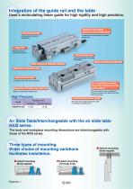
Integration of the guide rail and the table Uses a recirculating linear guide for high rigidity and high precision. Adjuster and piping placed on the same plane Positioning hole Located on the same plane to facilitate piping work. Improved body mounting repeatability Dual rod Twice the output of conventional cylinders Positioning hole Improved workpiece mounting repeatability Body mounting through-hole Wide variety of adjuster options Workpiece mounting tap Improved strength End plate uses extra super duralumin. It is possible to mount two auto switches on the same plane. Integration of table...
Open the catalog to page 2
Shock absorber (RB) can be mounted on 06 Shock absorber (soft type/short stroke RJ) can be mounted. (08 to 025) Improved cycle time, suitable for short strokes. Rubber stopper on both ends Extension stroke end shock absorber + Retraction stroke end ^ . rubber stopper Shock absorber on both ends Extension stroke end metal stopper + Retraction stroke end shock absorber Metal stopper on both ends T> Extension stroke end rubber stopper + „ Retraction stroke end - g metal stopper Variations Model Adjuster (Option) ( ) The MXQR6 series does not have a shock absorber type (J, JS, JT). Features...
Open the catalog to page 3
ISeries MXQR Enumerate the operating conditions considering the mounting position and workpiece configuration. Kinetic Energy Find the kinetic energy E (J) of the load. Find the allowable kinetic energy Ea (J). Confirm that the kinetic energy of the load does not exceed the allowable kinetic energy. 2 ( 1000 ) Co l l is io n speed V = 1.4 12 Va 2) Correction factor * (Reference Ea = K • E max values) Workpiece mounting coefficient K: Fig. (3) Max. allowable kinetic energy Emax: Table (1) Kinetic energy (E) < Allowable kinetic energy (Ea) Load FactorLoad Factor of Load Weight Wa = K • P • Wmax...
Open the catalog to page 4
Note) No need to consider this load factor in the case of using perpendicularly in a vertical position. Air Slide Table/Reversible Type Fig. (2) Overhang: Ln (mm), Series MXQR Fig. (3) Workpiece Mounting Coefficient: K Table mounting End plate mounting K = 0.6 Table (1) Allowable Kinetic Energy: Emax (J) A Caution • The maximum operating speed for the metal stopper type is 200 mm/s. • When the shock absorber type is mounted vertically, operate within the maximum allowable load weight range shown in Table (2). • The operating pressure range of the MXQR6 with shock absorber is 0.3 to 0.7 MPa. Table...
Open the catalog to page 5
* Buffer time: The time from when the product hits the rod end of the shock absorber to when the shock absorber reaches its retracted position. Operating pressure (MPa) MXQR12 Extension Stroke End ACaution 1. Operate loads within the range of the operating limits. Select the model considering maximum load weight and allowable moment. Refer to front matters 1 and 2 for the details. When actuator is used outside of operating limits, eccentric loads on guide will be in excess of this causing vibration on guide, inaccuracy, and shortened life. 2. If intermediate stops by external stopper is done,...
Open the catalog to page 6
Air Slide Table/Reversible Type Air Slide Table/ Reversible Type L 50 J M9BW TMade to Order Refer to page 2 for details. Port thread type Number of auto switches Nil Adjuster position set at the time of shipment 1 Nil Auto switch | Nil | Without auto switch (Built-in magnet) * For applicable auto switch models, refer to the below table. Right side Adjuster options * The adjuster position can be selected from two choices, right side and left side. It can be changed on site to suit the installation conditions. For detailed dimensions, refer to the product drawing. For the procedure for changing...
Open the catalog to page 7
Specifications ql J Made to Order I I" (For details, refer to pages 28 to 29.) * MXQR6 with shock absorber: Operating pressure 0.3 to 0.7 MPa Standard Stroke Model Theoretical Output OUT IN OUT The dual rod ensures an output twice that of existing cylinders. (N) Note) Theoretical output (N) = Pressure (MPa) x Piston area (mm2)
Open the catalog to page 8
Air Slide Table/Reversible Type Series MXQR Stroke Adjustment Range Optional Specifications Adjusters Three different types of adjusting bolt have been standardized for extension stroke end, retraction stroke end and both ends adjuster and cushion mechanisms. ■Rubber stopper Standard stroke adjuster ■Shock absorber Absorbs the impact at the stroke end for smooth stopping. Improved stopping accuracy. ■Metal stopper Improved stopping accuracy. Without cushioning function for use with light loads and low speeds. * Adjusters with wide adjustable range are available as option with rubber stopper and...
Open the catalog to page 9
Table Accuracy Shock Absorber Specifications Model Shock absorber model RJ Short Stroke Type Specifications Model Table (1) B Side Parallelism to A Side Shock absorber model Note) The shock absorber service life is different from that of the MXQR cylinder depending on the operating conditions. Refer to the RB/RJ series Specific Product Precautions for the replacement period. 1) B Side Traveling Parallelism to A Side (mm) Service Life and Replacement Period of Shock Absorber ACaution 1. Allowable operating cycle under the specifications set in this catalog is shown below. 1.2 million cycles RB0604-X2062,...
Open the catalog to page 10
2. Lateral Mounting (Through hole) 3. Vertical Mounting (Body tapped) 1. Do not scratch or dent the mounting side of the body, table or end plate. This can cause loss of parallelism in the mounting surfaces, vibration in the guide unit and increased operating resistance, etc. 2. Do not scratch or dent on the forward side of the rail or guide. This could result in looseness and increased operating resistance, etc. 3. Do not apply excessive power and load when a workpiece is mounted. If the external force more than the allowable moment were applied, looseness of the guide unit or increased operating...
Open the catalog to page 11All SMC Corporation of America catalogs and technical brochures
 LEHZ
LEHZ67 Pages
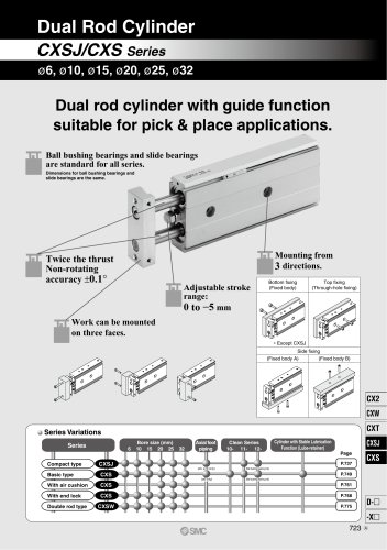 CXSJ
CXSJ60 Pages
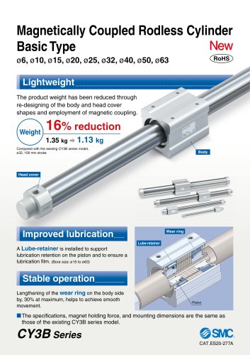 CY3B
CY3B17 Pages
 Aluminum High Vacuum Angle Valve
26 Pages
 AP Ultra High Purity
25 Pages
 IFW5 series
5 Pages
 Air Management System
64 Pages
 25A-ZSE20(F)/ISE20 Series
12 Pages
 ASG
ASG4 Pages
 IDG
IDG49 Pages
 CXSJ_M
2 Pages
 JLV20/30
8 Pages
 Series NCQ2/CQ2
252 Pages
 AC Series - Modular F.R.L. Units
70 Pages
 KQG2
KQG218 Pages
 IDF*E
IDF*E48 Pages
 AC10-A to AC40-A
82 Pages
 VQZ115, 100 Series
41 Pages
 SYJ300
60 Pages
 3000 Series
272 Pages
 MTS8
MTS823 Pages
 CXS-A
CXS-A60 Pages
 CXSL
CXSL60 Pages
 NC(D)Q2-Z
252 Pages
 LEY series
88 Pages
 MXH series
18 Pages
 KQ2
KQ2214 Pages
 Modular F.R.L. Units
108 Pages
 MXQ series
198 Pages
 Fieldbus System
92 Pages
 Fluoropolymer Piping Equipment
82 Pages
 Digital Flow Switch
24 Pages
 Vacuum Pad with Ejector
8 Pages
 Intrinsically safe Valve
43 Pages
 CQ2 series
25 Pages
 IDH, Thermo-dryer
12 Pages
 ISG
ISG10 Pages
 ISE3
ISE38 Pages
 ISE2
ISE27 Pages
 ISE1
ISE15 Pages
 ISA
ISA59 Pages
 IS3000
2 Pages
 IS10/10M/10E
4 Pages
 PSE series
44 Pages
 ISE70/75/75H
10 Pages
 ISE80
ISE8017 Pages
 ISE40A
29 Pages
 HED series
16 Pages
 HEC series
32 Pages
 HEB series
9 Pages
 HRG series
85 Pages
 HRZ series
52 Pages
 HRW series
28 Pages
 LQ series
35 Pages
 LVQ series catalog
75 Pages
 PA series
37 Pages
 EX600, Analog Input/Output Unit
59 Pages
 LER series
62 Pages
 LEJ series
58 Pages
 ISE/ZSE30A series
18 Pages
 LAT3 series
24 Pages
 LEH series
103 Pages
 CQS series
59 Pages
 CH series
175 Pages
 ARX series
12 Pages
 HRS series
47 Pages
 LES
LES59 Pages
 MHS
MHS74 Pages
 MHY
MHY27 Pages
 MHC
MHC27 Pages
 MHR
MHR30 Pages
 MHZ series
78 Pages
 MSQ
MSQ37 Pages
 MGP
MGP127 Pages
 MXS
MXS38 Pages
 NRB
NRB10 Pages
 MXW
MXW22 Pages
 MHT
MHT11 Pages
 MY3
MY354 Pages
 CQM
CQM15 Pages
 NCA1
NCA163 Pages
 CM2
CM2152 Pages
 NCM
NCM91 Pages
 NCG
NCG96 Pages
 NCRA1
NCRA15 Pages
 CS2
CS232 Pages
 T/TIA
T/TIA1 Page
 KR
KR7 Pages
 KF
KF16 Pages
 KQ
KQ80 Pages
 AFF
AFF80 Pages
 AMG
AMG80 Pages
 IDF
IDF16 Pages
 HAA
HAA3 Pages
 ZFA
ZFA14 Pages
 ZA
ZA13 Pages
 MHF
MHF32 Pages
 CRB
CRB44 Pages
 D
D117 Pages
 RB
RB23 Pages
 CEP
CEP44 Pages
 rsq
rsq30 Pages
 CLK
CLK51 Pages
 MK
MK20 Pages
 CLJ
CLJ65 Pages
 MGJ
MGJ7 Pages
 ZSE30A
17 Pages
 IDFB*E
89 Pages
 ISE10
ISE1016 Pages
 ITV1000/2000
50 Pages
 AW
AW27 Pages
 NVFM200
12 Pages
 NVM100
32 Pages
 LLA*A
LLA*A36 Pages
 VX3*
VX3*41 Pages
 SY3000
158 Pages
 CH(D)2
175 Pages
 M(D)SUB
31 Pages


Archived catalogs
 Rodless cylinder
52 Pages
 ZSE1 series
12 Pages
 Rack and Pinion Rotary Actuators
37 Pages
 Special Fittings
14 Pages
 Toggle Grippers
16 Pages
 SX series
138 Pages
 ACG series
25 Pages
 C95 Pneumatic Cylinder
50 Pages
 Shock Absorber
16 Pages
 Silencer
4 Pages
 VV061 series
11 Pages
 Air Filter Catalog
18 Pages
 heavy Duty Actuators
88 Pages
 Self-seal Fittings Catalog
13 Pages
 Connectors Catalog
53 Pages

