- Products
- Catalogs
- News & Trends
- Exhibitions
MK
1 /20Pages

MK
1 /20Pages
Catalog excerpts

Rotary Clamp Cylinder Allowable moment of inertia 3 times higher New structure! MK series is released!! Overall length is the same as the existing products! Mounting dimensions are interchangeable with the MK series. Possible to mount small auto switches on 4 surfaces • Auto switches can be mounted on any of the 4 surfaces to suit the installation conditions (2 surfaces for o20 and o25). • No projection of auto switch Rotary stroke 2-color indication solid state auto switch Accurate setting of the mounting position can be performed without mistakes A *TEpt light indicates the proper ^^^^^^ operating range. operating range Application Example Clamp stroke
Open the catalog to page 1
Allowable moment of inertia 3 times higher Allowable moment of inertia is the same as Allowable Moment of Inertia (032, 040) (Heavy-duty type) Piston speed [trim's] Maintenance can be performed for all sizes. Seal kit and guide pin are replaceable. Magnetic field resistant auto ^ Standard stroke range has been expanded. Strokes have been added to the New MK series, making a wide range of strokes available. ("^ indicates the added strokes.) Head flanges are newly Mounting type has been added to suit a wide range of applications. Overall length is shortened. 3 tO 10 mm shorter than the MK2 series,...
Open the catalog to page 2
Model Selection Max. piston speed Note) [mm/s] o12 to o63 Non-rotating accuracy (Clamp part) Rotary angle Horizontal mounting Note) Maximum piston speed indicates the maximum speed possible when employing a standard arm. During unclamping Rotary angle Port side During unclamping Rotary angle During clamping (Retraction end) Non-rotating accuracy Designing Arms When arms are to be made separately, their length and mass should be within the following range. 1. Allowable bending moment Use the arm length and operating pressure within Graph (1) for allowable bending moment loaded piston rod. Operating...
Open the catalog to page 3
Bore Size Selection Note) Maximum piston speed is equivalent to approximately 1.6x the average piston speed. (Rough Indication) Calculate the operating conditions and operate this product within the allowable range. If the allowable range is exceeded, increase the bore size or use the MK2T series. (Refer to SMC Best Pneumatics No. 3 for details of the MK2T series.) Maximum piston speed [mm/s] Maximum piston speed [mm/s] Maximum piston speed [mm/s] Maximum piston speed [mm/s]
Open the catalog to page 4
Bore Size Selection Note) Maximum piston speed is equivalent to approximately 1.6x the average piston speed. (Rough Indication) Calculation example when arms other than the options are used. • Calculate the moment of inertia of the clamping jig • Calculate the moment of inertia of the arm. ■(Calculation example> when the cylinder bore Size ÍS 032. Clamping jig: h • Calculate the actual moment of inertia. Calculation result (when the bore size is o32 and clamp stroke is 10 mm.) Note 1) Average piston speed = Max. piston speed -M .6 Note 2) Total stroke = Clamp stroke + Rotary stroke Note 3) Total...
Open the catalog to page 5
Bore Size Selection Do not use the cylinder under the following environments: • An area in which fluids such as cutting oil splash on the piston rod • An area in which foreign matter such as particles, cutting chips, or dust is present • An area in which the ambient temperature exceeds the operating range • An area exposed to direct sunlight • An environment that poses the risk of corrosion A cylinder could malfunction or the non-rotating accuracy could be affected if a rotational force is applied to the piston rod. Therefore, observe the particulars given below before operating the cy- 1) Make...
Open the catalog to page 6
Rotary Clamp Cylinder: Standard Rotary clamp cylinder Mounting bracket ■ Head flanges are shipped together, (but Bore size* Port thread type Clamp stroke (Refer to the next page Auto switch type •Auto switch type Auto switch multiple side mounting Without auto switch (Built-in magnet) Body option ■ For applicable auto switch models. refer to the below table. ■ Auto switches are shipped * Arms are shipped together, (but not Rotary direction (Unclamp -» Clamp) During unclamping During unclamping During clamping (Retraction end) Applicable Auto Switches/Refer to Best Pneumatics No. 3 for further...
Open the catalog to page 7
Rotary Angle During unclamping During unclamping Clamp part / \ Non-rotating accuracy During clamping (Retraction end) (Fordetails, referto page 17.] Mounting Bracket/Flange Note 1 ) Refer to Rotary Angle figure. Note 2) Direction of rotation viewed from the rod end when the piston rod is retracting Note 3) Clamp force at 0.5 MPa Note 4) When using the cylinder within a pressure range from 0.61 to 1 MPa, please use -X2071. Note 5) Be sure to install a speed controller to the cylinder, and adjust the cylinder speed to make it within the range from 50 to 200 mm/s. To adjust the speed, start with...
Open the catalog to page 8
Rotary Clamp Cylinder: Standard Series MK Mounting Bolt for MKB-Z Mounting: Mounting bolt for through-hole type is available. Refer to the following for ordering procedures. Order the actual number of bolts that will be used. Mounting boll Flat washer/ Note) Be sure to use a flat washer to mount cylinders via through-holes. Use a clamp arm that is available as an option. To fabricate a clamp arm, make sure that the allowable bending moment and the inertial moment will be within the specified range. Refer to Graph 1 and 2 on page 1. Ensuring Safety If one side of the piston is pressurized by supplying...
Open the catalog to page 9
Component Parts Component Parts * Seal kit includes numbers in the table. Order the seal kit, based on each bore size. * Since the seal kit does not include a grease pack, order it separately. Grease pack part no.: GR-S-010 (10 g) Guide pin kit includes numbers in the table. Order the guide pin kit, based on each bore size. For the replacement procedure of the replacement parts/seal and guide pin kits, refer to the Operation Manual.
Open the catalog to page 10
Rotary Clamp Cylinder: Standard Series MK The outline dimensions shown are when the rod is retracted. Through-hole/Both ends tapped common E effective thread depth F Auto switch Minimum bending radius Note) The above figure is with the auto switch (D-M9D) mounted. Rotary direction: L ^orl side Rotary direction: R During unclamping During unclamping During clamping Head flange Head Flange
Open the catalog to page 11All SMC Corporation of America catalogs and technical brochures
 LEHZ
LEHZ67 Pages
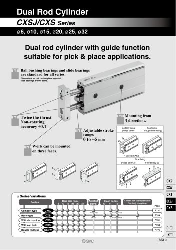 CXSJ
CXSJ60 Pages
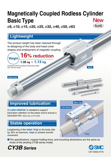 CY3B
CY3B17 Pages
 Aluminum High Vacuum Angle Valve
26 Pages
 AP Ultra High Purity
25 Pages
 IFW5 series
5 Pages
 Air Management System
64 Pages
 25A-ZSE20(F)/ISE20 Series
12 Pages
 ASG
ASG4 Pages
 IDG
IDG49 Pages
 CXSJ_M
2 Pages
 JLV20/30
8 Pages
 Series NCQ2/CQ2
252 Pages
 AC Series - Modular F.R.L. Units
70 Pages
 KQG2
KQG218 Pages
 IDF*E
IDF*E48 Pages
 AC10-A to AC40-A
82 Pages
 VQZ115, 100 Series
41 Pages
 SYJ300
60 Pages
 3000 Series
272 Pages
 MTS8
MTS823 Pages
 CXS-A
CXS-A60 Pages
 CXSL
CXSL60 Pages
 MXQR
MXQR36 Pages
 NC(D)Q2-Z
252 Pages
 LEY series
88 Pages
 MXH series
18 Pages
 KQ2
KQ2214 Pages
 Modular F.R.L. Units
108 Pages
 MXQ series
198 Pages
 Fieldbus System
92 Pages
 Fluoropolymer Piping Equipment
82 Pages
 Digital Flow Switch
24 Pages
 Vacuum Pad with Ejector
8 Pages
 Intrinsically safe Valve
43 Pages
 CQ2 series
25 Pages
 IDH, Thermo-dryer
12 Pages
 ISG
ISG10 Pages
 ISE3
ISE38 Pages
 ISE2
ISE27 Pages
 ISE1
ISE15 Pages
 ISA
ISA59 Pages
 IS3000
2 Pages
 IS10/10M/10E
4 Pages
 PSE series
44 Pages
 ISE70/75/75H
10 Pages
 ISE80
ISE8017 Pages
 ISE40A
29 Pages
 HED series
16 Pages
 HEC series
32 Pages
 HEB series
9 Pages
 HRG series
85 Pages
 HRZ series
52 Pages
 HRW series
28 Pages
 LQ series
35 Pages
 LVQ series catalog
75 Pages
 PA series
37 Pages
 EX600, Analog Input/Output Unit
59 Pages
 LER series
62 Pages
 LEJ series
58 Pages
 ISE/ZSE30A series
18 Pages
 LAT3 series
24 Pages
 LEH series
103 Pages
 CQS series
59 Pages
 CH series
175 Pages
 ARX series
12 Pages
 HRS series
47 Pages
 LES
LES59 Pages
 MHS
MHS74 Pages
 MHY
MHY27 Pages
 MHC
MHC27 Pages
 MHR
MHR30 Pages
 MHZ series
78 Pages
 MSQ
MSQ37 Pages
 MGP
MGP127 Pages
 MXS
MXS38 Pages
 NRB
NRB10 Pages
 MXW
MXW22 Pages
 MHT
MHT11 Pages
 MY3
MY354 Pages
 CQM
CQM15 Pages
 NCA1
NCA163 Pages
 CM2
CM2152 Pages
 NCM
NCM91 Pages
 NCG
NCG96 Pages
 NCRA1
NCRA15 Pages
 CS2
CS232 Pages
 T/TIA
T/TIA1 Page
 KR
KR7 Pages
 KF
KF16 Pages
 KQ
KQ80 Pages
 AFF
AFF80 Pages
 AMG
AMG80 Pages
 IDF
IDF16 Pages
 HAA
HAA3 Pages
 ZFA
ZFA14 Pages
 ZA
ZA13 Pages
 MHF
MHF32 Pages
 CRB
CRB44 Pages
 D
D117 Pages
 RB
RB23 Pages
 CEP
CEP44 Pages
 rsq
rsq30 Pages
 CLK
CLK51 Pages
 CLJ
CLJ65 Pages
 MGJ
MGJ7 Pages
 ZSE30A
17 Pages
 IDFB*E
89 Pages
 ISE10
ISE1016 Pages
 ITV1000/2000
50 Pages
 AW
AW27 Pages
 NVFM200
12 Pages
 NVM100
32 Pages
 LLA*A
LLA*A36 Pages
 VX3*
VX3*41 Pages
 SY3000
158 Pages
 CH(D)2
175 Pages
 M(D)SUB
31 Pages


Archived catalogs
 Rodless cylinder
52 Pages
 ZSE1 series
12 Pages
 Rack and Pinion Rotary Actuators
37 Pages
 Special Fittings
14 Pages
 Toggle Grippers
16 Pages
 SX series
138 Pages
 ACG series
25 Pages
 C95 Pneumatic Cylinder
50 Pages
 Shock Absorber
16 Pages
 Silencer
4 Pages
 VV061 series
11 Pages
 Air Filter Catalog
18 Pages
 heavy Duty Actuators
88 Pages
 Self-seal Fittings Catalog
13 Pages
 Connectors Catalog
53 Pages

