MHY
1 /27Pages

MHY
1 /27Pages
Catalog excerpts

P0655-P0714-E.qxd 08.9.29 3:42 PM Page 655 180° Angular Style Air Gripper Series MHY2 /MHW2 Cam Style / Rack & Pinion Style MHZ MHF MHL MHR MHK MHS MHC MHT MHY MHW -X MRHQ MA D- 655
Open the catalog to page 1
180° Angular Style Air Gripper Cam Style Rack & Pinion Style Light and compact size in small bore sizes Improved mounting repeatability Resistance to dusty environments Reduced opening sizes helps prevent foreign objects from entering. Auto switch mounting Stainless steel Rack & Pinion
Open the catalog to page 2
180° Angular Style Air Gripper Series MHY2/MHW2 Series MHW2/Rack & Pinion Style Unique seal design allows shorter total length construction and constant grippng force when opening and closing fingers, (PAT.PEND) Auto switch mounting Key connection between finger and shaft prevents finger angle slippage during impact. Two finger styles available. Flat finger type Right angle finger type Dustproof construction Seal arrangement protects gripper from harsh dusty environments.
Open the catalog to page 3
P0655-P0714-E.qxd 08.9.29 3:42 PM Page 658 Series MHY2/MHW2 Model Selection Model Selection Selection Procedure Step 1 Confirmation of gripping force Step 1 Step 2 Confirmation of gripping point Step 3 Confirmation of moment of inertia of attachments Confirmation of Gripping Force Confirmation of conditions Calculation of required gripping force Selection of model from gripping force graph Example MHY2-16D Guidelines for the selection of the gripper with respect to component weight 25 Pressure 0.6 MPa 20 0.5 Gripping force (N) Workpiece weight: 0.05 kg • Although conditions differ according to...
Open the catalog to page 4
P0655-P0714-E.qxd 08.9.29 3:42 PM Page 659 180° Angular Style Air Gripper MHW2-32D 25 0.6 Gripping force (N) Gripping force (N) Pressure 0.7 MPa 0.5 15 0.4 0.3 10 0.2 5 0 20 40 60 80 80 60 20 0 Pressure 0.7 MPa Pressure 0.7 MPa 250 0.6 0.5 0.3 0.2 200 150 100 0.6 0.5 0.4 0.3 0.2 50 20 40 60 80 100 0 120 40 MHW2-25D 80 120 160 200 Gripping point L (mm) Gripping point L (mm) Gripping point L (mm) MHW2-40D 160 50 Pressure 0.7 MPa 0.5 30 0.4 0.3 20 Pressure 0.7 MPa 140 0.6 40 Gripping force (N) Gripping force (N) MHW2-50D 0.4 40 MHY2/MHW2 300 100 Gripping force (N) MHW2-20D 20 Series 0.2 10 120 100...
Open the catalog to page 5
Model Selection Confirmation of Moment of Inertia of Attachments Confirm the moment of inertia for the attachment at one side. Calculate the moment of inertia for A and B separately as shown in the figures on the right. Calculation example 1. Check the operating conditions, 2. Calculate the moment of inertia mi = axbxcx Specific gravity Moment of inertia around Zi axis Moment of inertia around Z axis Moment of inertia around Z2 axis Moment of inertia around Z axis Total moment of inertia I = IA + IB /* Constant for unit conversion) Material of attachment: Aluminum alloy 3. Determine the allowable...
Open the catalog to page 6
180° Angular Style Air Gripper Series MHY2/MHW2 Allowable Range of Moment of
Open the catalog to page 7
180° Angular Style Air Gripper Bore size • Refer to page 663 for details. Number of auto switches Auto switch Without auto switch (Built-in magnet) t For the applicable auto switch model, refer to the table below. Finger option Double acting Nil: Standard tapped 2: Through-holes in mounting opening/closing direction Applicable Auto Switch / Refer to pages 761 to 809 for further information on auto switches Note 1) Take note of hysteresis with 2-color indication type switches. Refer to page 678 for detailed auto switch specifications. : Auto switches marked with a "O" symbol are produced upon...
Open the catalog to page 8
180° Angular Style Air Gripper , j|jff_fi/o Note) Refer to pages 761 to 809 for further information on auto switches. j) Note 2) Except auto switch Refer to "How to Select the Applicable Model" on page 658. Refer to pages 658 and 659 for the details on effective holding force and allowable overhanging distance. "order | Made to Order (Refer to pages 683 to 713 for details.)
Open the catalog to page 9
Closed condition Open condition Component Parts Replacement Parts * Order 1 piece of finger assembly per one unit. Replacement part/grease pack part no. : MH-G04 (30g)
Open the catalog to page 10
180° Angular Style Air Gripper , j|jff_fi/o .(Thread for mounting attachment) (Mounting thread) (Mounting thread) (Mounting hole) (Mounting thread) Auto Switch Mounting Groove Dimensions (Finger closing port) Opening/Closing direction through-hole type ^(Hole for mounting attachment) * Do not extend the attachment from limited area for mounting to avoid interference with the attachment or main body.
Open the catalog to page 11
(Mounting thread) (Mounting thread) (Mounting thread) (Finger closing port) Opening/Closing direction through-hole type Auto Switch Mounting Groove Dimensions (Hole for mounting attachment) * Do not extend the attachment from limited area for mounting to avoid interference with the attachment or main body.
Open the catalog to page 12
180° Angular Style Air Gripper , j|jff_fi/o . (Thread for mounting attachment) (Mounting thread) nting thread) (Mounting thread) (Finger opening port)x (Finger closing port) Auto Switch Mounting Groove Dimensions Opening/Closing direction through-hole type \(Hole for mounting attachment) * Do not extend the attachment from limited area for mounting to avoid interference with the attachment or main body.
Open the catalog to page 13
P0655-P0714-E.qxd Series 08.9.29 3:42 PM Page 668 MHY2 Dimensions MHY2-25D 2 x M6 x 1 thread depth 10 Pin hole positioning 50 23 5 16 (Mounting thread) 4H9 + 0.030 depth4 0 4 x M5 x 0.8 through (Thread for mounting attachment) 10 —0.005 —0.025 4 x M6 x 1 thread depth 12 (Mounting thread) 6 12 (Mounting thread) 58 46 42 45 45 12 (Limted area for mounting attachment∗) 2 x M6 x 1 thread depth 12 (Mounting hole) 22.5 2 x ø6.6 through ø26H9 + 0.052 depth1.5 0 30 Positioning pin hole 60 18 5 86 30 107 Auto Switch Mounting Groove Dimensions 24 14 M5 x 0.8 (Finger opening port) 8 ø4 42 3 M5 x 0.8 (Finger...
Open the catalog to page 14
180° Angular Style Air Gripper Rack & Pinion Style Port thread type Refer to page 670 for details. Number of auto switches Auto switch Without auto switch (Built-in magnet) For the applicable auto switch model, refer to the table below. Finger option Nil: Flat type fingers 1: Right angle type fingers (Standard) tapped mounting Applicable Auto Switch / Refer to pages 761 to 809 for further information on auto switches. Note 1) Take note of hysteresis with 2-color indication type switches. ■ Auto switches marked with a "O" symbol are produced upon receipt of order.
Open the catalog to page 15All SMC Corporation of America catalogs and technical brochures
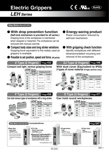 LEHZ
LEHZ67 Pages
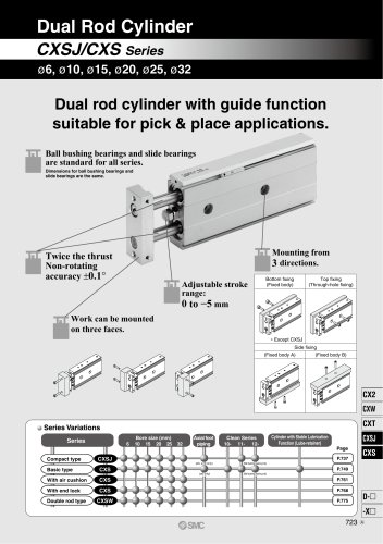 CXSJ
CXSJ60 Pages
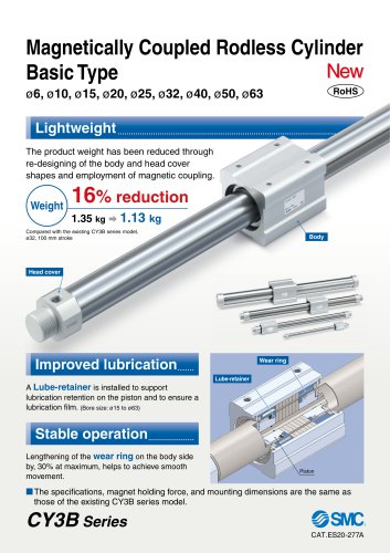 CY3B
CY3B17 Pages
 Aluminum High Vacuum Angle Valve
26 Pages
 AP Ultra High Purity
25 Pages
 IFW5 series
5 Pages
 Air Management System
64 Pages
 25A-ZSE20(F)/ISE20 Series
12 Pages
 ASG
ASG4 Pages
 IDG
IDG49 Pages
 CXSJ_M
2 Pages
 JLV20/30
8 Pages
 Series NCQ2/CQ2
252 Pages
 AC Series - Modular F.R.L. Units
70 Pages
 KQG2
KQG218 Pages
 IDF*E
IDF*E48 Pages
 AC10-A to AC40-A
82 Pages
 VQZ115, 100 Series
41 Pages
 SYJ300
60 Pages
 3000 Series
272 Pages
 MTS8
MTS823 Pages
 CXS-A
CXS-A60 Pages
 CXSL
CXSL60 Pages
 MXQR
MXQR36 Pages
 NC(D)Q2-Z
252 Pages
 LEY series
88 Pages
 MXH series
18 Pages
 KQ2
KQ2214 Pages
 Modular F.R.L. Units
108 Pages
 MXQ series
198 Pages
 Fieldbus System
92 Pages
 Fluoropolymer Piping Equipment
82 Pages
 Digital Flow Switch
24 Pages
 Vacuum Pad with Ejector
8 Pages
 Intrinsically safe Valve
43 Pages
 CQ2 series
25 Pages
 IDH, Thermo-dryer
12 Pages
 ISG
ISG10 Pages
 ISE3
ISE38 Pages
 ISE2
ISE27 Pages
 ISE1
ISE15 Pages
 ISA
ISA59 Pages
 IS3000
2 Pages
 IS10/10M/10E
4 Pages
 PSE series
44 Pages
 ISE70/75/75H
10 Pages
 ISE80
ISE8017 Pages
 ISE40A
29 Pages
 HED series
16 Pages
 HEC series
32 Pages
 HEB series
9 Pages
 HRG series
85 Pages
 HRZ series
52 Pages
 HRW series
28 Pages
 LQ series
35 Pages
 LVQ series catalog
75 Pages
 PA series
37 Pages
 EX600, Analog Input/Output Unit
59 Pages
 LER series
62 Pages
 LEJ series
58 Pages
 ISE/ZSE30A series
18 Pages
 LAT3 series
24 Pages
 LEH series
103 Pages
 CQS series
59 Pages
 CH series
175 Pages
 ARX series
12 Pages
 HRS series
47 Pages
 LES
LES59 Pages
 MHS
MHS74 Pages
 MHC
MHC27 Pages
 MHR
MHR30 Pages
 MHZ series
78 Pages
 MSQ
MSQ37 Pages
 MGP
MGP127 Pages
 MXS
MXS38 Pages
 NRB
NRB10 Pages
 MXW
MXW22 Pages
 MHT
MHT11 Pages
 MY3
MY354 Pages
 CQM
CQM15 Pages
 NCA1
NCA163 Pages
 CM2
CM2152 Pages
 NCM
NCM91 Pages
 NCG
NCG96 Pages
 NCRA1
NCRA15 Pages
 CS2
CS232 Pages
 T/TIA
T/TIA1 Page
 KR
KR7 Pages
 KF
KF16 Pages
 KQ
KQ80 Pages
 AFF
AFF80 Pages
 AMG
AMG80 Pages
 IDF
IDF16 Pages
 HAA
HAA3 Pages
 ZFA
ZFA14 Pages
 ZA
ZA13 Pages
 MHF
MHF32 Pages
 CRB
CRB44 Pages
 D
D117 Pages
 RB
RB23 Pages
 CEP
CEP44 Pages
 rsq
rsq30 Pages
 CLK
CLK51 Pages
 MK
MK20 Pages
 CLJ
CLJ65 Pages
 MGJ
MGJ7 Pages
 ZSE30A
17 Pages
 IDFB*E
89 Pages
 ISE10
ISE1016 Pages
 ITV1000/2000
50 Pages
 AW
AW27 Pages
 NVFM200
12 Pages
 NVM100
32 Pages
 LLA*A
LLA*A36 Pages
 VX3*
VX3*41 Pages
 SY3000
158 Pages
 CH(D)2
175 Pages
 M(D)SUB
31 Pages


Archived catalogs
 Rodless cylinder
52 Pages
 ZSE1 series
12 Pages
 Rack and Pinion Rotary Actuators
37 Pages
 Special Fittings
14 Pages
 Toggle Grippers
16 Pages
 SX series
138 Pages
 ACG series
25 Pages
 C95 Pneumatic Cylinder
50 Pages
 Shock Absorber
16 Pages
 Silencer
4 Pages
 VV061 series
11 Pages
 Air Filter Catalog
18 Pages
 heavy Duty Actuators
88 Pages
 Self-seal Fittings Catalog
13 Pages
 Connectors Catalog
53 Pages

