- Products
- Catalogs
- News & Trends
- Exhibitions
MHF
1 /32Pages

MHF
1 /32Pages
Catalog excerpts

Low profile air gripper with space-saving design
Open the catalog to page 1
Height is approximately 1/3 the size of ■The low profile design saves space and reduces bending ■ improved accuracy with smooth • Reduced bending moment and vibration Stroke selection is available. 3 standard stroke lengths are available for each bore size. Stroke can be selected to suit the workpiece.
Open the catalog to page 2
Improved mounting repeatability Piping is available from 2 directions Piping port position can be specified using a part number. Linear guide provides martensitic stainless steel mounting attachments With positioning pin holes Centralized wiring and piping are possible. Axial piping Side piping High degree of mounting flexibility As no brackets are required, mounting height Strong gripping force Double piston construction achieves compact design with strong gripping force.
Open the catalog to page 3
Model Selection Model Selection Selection Procedure Confirm gripping force Confirm gripping point Confirm external force on fingers Confirmation of Gripping Force- •\ Calculation of required gripping force ►(Model selection from gripping force graph) Example Workpiece mass: 0.15 kg Gripping method: External Model selection criteria with respect to workpiece mass • Although differences will exist depending on factors such as shape and the coefficient of friction between attachments and workpieces, select a model which will provide a gripping force 10 to 20 times the weight of the workpiece. (Notel)...
Open the catalog to page 4
Low Profile Air Gripper Series MHF2 Effective Gripping Force: Series MHF2 ■ Expressing the effective grip- ping force The effective gripping force shown in the graphs below is thrust of one finger when both full contact with the workpiece as shown in the figure below. External Gripping Internal Gripping
Open the catalog to page 5
Model Selection Effective Gripping Force: Series MHF2- External Gripping Internal Gripping • The air gripper should be operated so that the amount of overhang "H" will stay within the range given in the graphs below. • If the workpiece gripping point goes beyond the range limits, this will have an adverse effect on the life of the air gripper.
Open the catalog to page 6
Low Profile Air Gripper Seríes MHF2 Confirmation of External Force on Fingers: Series MHF2 L: Distance to the point at which the load is applied (mm) Note) The load and moment values in the table indicate static values. Calculation of allowable external force (when moment load is applied) M (Maximum allowable moment) (N m) (* Unit converted invariable number) Calculation example When a load f = 10 N is operating, which applies pitch moment to point L = 30 mm from the end of the
Open the catalog to page 7
Refer to page 453 for details. Number of auto switches Auto switch Without auto switch (Built-in magnet) Body option Nil: Axial piping type R: Side piping type Applicable Auto Switches/Refer to pages 761 to 809 for further Information on auto switches. Note 1) Take note of hysteresis with 2-color indication type switches. When using, refer to page 471 for auto switch hysteresis.
Open the catalog to page 8
Low Profile Air Gripper Seríes MHF2 Note 1) This is the value when no offset load is applied to the finger. When an offset load is applied to the finger, the maximum value is ±0.15 mm due to the influence of backlash of the rack and pinion. Note 2) Refer to pages 761 to 809 for further information on auto switches. Note 1) At the pressure of 0.5 MPa, when gripping point L is 20 mm. MHK Note 2) Excluding the auto switch mass. ^=== Made to Order |y|HQ Refer to pages 683 to 713 for details.
Open the catalog to page 9
Component Parts Replacement Parts Component Parts Bolts for Body Through-hole Replacement part/Grease pack part no.: * The bolts for body through-hole mounting are attached to the product. They are also provided at an order of 1 piece or more with the above part numbers.
Open the catalog to page 10
Low Profile Air Gripper Seríes MHF2 Component Parts Replacement Parts Bolts for Body Through-hole The bolts for body through-hole mounting are attached to the product. They are also provided at an order of 1 piece or more with the above part numbers. with the body through-holes, use hexagon socket head screws available on the market. Replacement part/Grease pack part no.:
Open the catalog to page 11
(Mounting thread) Finger opening port Finger closing port (Mounting thread) Auto Switch Mounting Groove Dimensions .auto switch mounting (Mounting thread) * Use the attached hexagon socket head screws for mounting holes. (Attachment mounting thread) Accessory option: Hexagon socket head screw (special screws) '(Mounting thread)
Open the catalog to page 12
Low Profile Air Gripper Seríes MHF2 (Mounting thread) Finger opening port Auto Switch Mounting Groove Dimensions (Mounting thread) auto switch mounting (Mounting thread) : Use the attached hexagon socket head screws for mounting holes. (Attachment mounting thread) Accessory option: Hexagon socket head screw (special screws) '(Mounting thread)
Open the catalog to page 13
(Mounting thread) Finger opening port Use the attached hexagon socket head screws for mounting holes. (Mounting thread) Auto Switch Mounting Groove Dimensions auto switch mounting ' (Attachment mounting thread) Accessory option: Hexagon socket head screw (special screws) '(Mounting thread)
Open the catalog to page 14
Low Profile Air Gripper Seríes MHF2 (Mounting thread) Finger opening port Finger closing port Auto Switch Mounting Groove Dimensions (Mounting thread) ' (Mounting thread) : Use the attached hexagon socket head screws for mounting holes. (Attachment mounting thread) Accessory option: Hexagon socket head screw (special screws) (Mounting thread)
Open the catalog to page 15
Series MHF2 Dimensions depth 3 MHF2-12D1 42 +0.025 0 depth 3 3H9 ø3H9 +0.030 0 0.3 10.6 2 x M4 x 0.7 thread depth 10 (Mounting thread) 4 58 4 Detail of part A 40 68 2 x M4 x 0.7 thread depth 5 54 15 25 19 20 A (Mounting thread) E 7.7 20 14.8 M5 x 0.8 Finger closing port E 0 –0.1 21 1 1 M5 x 0.8 Finger opening port 2 x ø3.4 through (Mounting hole)∗ 21 2 x ø5.5 +0.1 Close: 0 0 E-E Open: 24±1 ∗ Use the attached hexagon socket head screws for mounting holes. 8 x M3 x 0.5 thread depth 4 44 4 x M4 x 0.7 thread depth 5 (Mounting thread) (Attachment mounting thread) M3 x 0.5 ø5 Auto Switch Mounting Groove...
Open the catalog to page 16All SMC Corporation of America catalogs and technical brochures
 LEHZ
LEHZ67 Pages
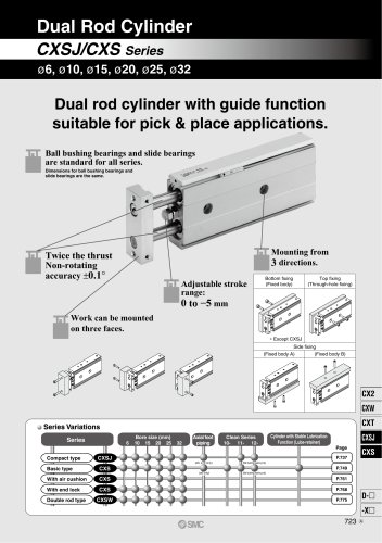 CXSJ
CXSJ60 Pages
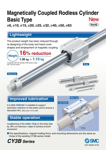 CY3B
CY3B17 Pages
 Aluminum High Vacuum Angle Valve
26 Pages
 AP Ultra High Purity
25 Pages
 IFW5 series
5 Pages
 Air Management System
64 Pages
 25A-ZSE20(F)/ISE20 Series
12 Pages
 ASG
ASG4 Pages
 IDG
IDG49 Pages
 CXSJ_M
2 Pages
 JLV20/30
8 Pages
 Series NCQ2/CQ2
252 Pages
 AC Series - Modular F.R.L. Units
70 Pages
 KQG2
KQG218 Pages
 IDF*E
IDF*E48 Pages
 AC10-A to AC40-A
82 Pages
 VQZ115, 100 Series
41 Pages
 SYJ300
60 Pages
 3000 Series
272 Pages
 MTS8
MTS823 Pages
 CXS-A
CXS-A60 Pages
 CXSL
CXSL60 Pages
 MXQR
MXQR36 Pages
 NC(D)Q2-Z
252 Pages
 LEY series
88 Pages
 MXH series
18 Pages
 KQ2
KQ2214 Pages
 Modular F.R.L. Units
108 Pages
 MXQ series
198 Pages
 Fieldbus System
92 Pages
 Fluoropolymer Piping Equipment
82 Pages
 Digital Flow Switch
24 Pages
 Vacuum Pad with Ejector
8 Pages
 Intrinsically safe Valve
43 Pages
 CQ2 series
25 Pages
 IDH, Thermo-dryer
12 Pages
 ISG
ISG10 Pages
 ISE3
ISE38 Pages
 ISE2
ISE27 Pages
 ISE1
ISE15 Pages
 ISA
ISA59 Pages
 IS3000
2 Pages
 IS10/10M/10E
4 Pages
 PSE series
44 Pages
 ISE70/75/75H
10 Pages
 ISE80
ISE8017 Pages
 ISE40A
29 Pages
 HED series
16 Pages
 HEC series
32 Pages
 HEB series
9 Pages
 HRG series
85 Pages
 HRZ series
52 Pages
 HRW series
28 Pages
 LQ series
35 Pages
 LVQ series catalog
75 Pages
 PA series
37 Pages
 EX600, Analog Input/Output Unit
59 Pages
 LER series
62 Pages
 LEJ series
58 Pages
 ISE/ZSE30A series
18 Pages
 LAT3 series
24 Pages
 LEH series
103 Pages
 CQS series
59 Pages
 CH series
175 Pages
 ARX series
12 Pages
 HRS series
47 Pages
 LES
LES59 Pages
 MHS
MHS74 Pages
 MHY
MHY27 Pages
 MHC
MHC27 Pages
 MHR
MHR30 Pages
 MHZ series
78 Pages
 MSQ
MSQ37 Pages
 MGP
MGP127 Pages
 MXS
MXS38 Pages
 NRB
NRB10 Pages
 MXW
MXW22 Pages
 MHT
MHT11 Pages
 MY3
MY354 Pages
 CQM
CQM15 Pages
 NCA1
NCA163 Pages
 CM2
CM2152 Pages
 NCM
NCM91 Pages
 NCG
NCG96 Pages
 NCRA1
NCRA15 Pages
 CS2
CS232 Pages
 T/TIA
T/TIA1 Page
 KR
KR7 Pages
 KF
KF16 Pages
 KQ
KQ80 Pages
 AFF
AFF80 Pages
 AMG
AMG80 Pages
 IDF
IDF16 Pages
 HAA
HAA3 Pages
 ZFA
ZFA14 Pages
 ZA
ZA13 Pages
 CRB
CRB44 Pages
 D
D117 Pages
 RB
RB23 Pages
 CEP
CEP44 Pages
 rsq
rsq30 Pages
 CLK
CLK51 Pages
 MK
MK20 Pages
 CLJ
CLJ65 Pages
 MGJ
MGJ7 Pages
 ZSE30A
17 Pages
 IDFB*E
89 Pages
 ISE10
ISE1016 Pages
 ITV1000/2000
50 Pages
 AW
AW27 Pages
 NVFM200
12 Pages
 NVM100
32 Pages
 LLA*A
LLA*A36 Pages
 VX3*
VX3*41 Pages
 SY3000
158 Pages
 CH(D)2
175 Pages
 M(D)SUB
31 Pages


Archived catalogs
 Rodless cylinder
52 Pages
 ZSE1 series
12 Pages
 Rack and Pinion Rotary Actuators
37 Pages
 Special Fittings
14 Pages
 Toggle Grippers
16 Pages
 SX series
138 Pages
 ACG series
25 Pages
 C95 Pneumatic Cylinder
50 Pages
 Shock Absorber
16 Pages
 Silencer
4 Pages
 VV061 series
11 Pages
 Air Filter Catalog
18 Pages
 heavy Duty Actuators
88 Pages
 Self-seal Fittings Catalog
13 Pages
 Connectors Catalog
53 Pages

