
- Catalogs
- SMC Corporation of America
- LEY series


LEY series

LEY series
Catalog excerpts

LEY Series Rod Type/Guide Rod Type [Step Motor (Servo/24 vooHservo Motor (24 vdc| Type Rod Type LEY Series Long stroke: Max. 500 mm (LEY32, 40) Mounting variations •Direct mounting: 3 directions, Bracket mounting: 3 types •Either positioning or pushing control can be selected. Possible to hold the actuator with the rod pushing to a workpiece, etc Guide Rod Type LEYG Series Lateral end load: 5 times more * Compared with rod type, size 25 and 100 mm stroke Compatible with sliding bearing and ball bushing bearing. Compatible with moment load and stopper (sliding bearing). •Either positioning or pushing control can be selected. Possible to hold the actuator with the rod pushing to a workpiece, etc. Rod Type LEY Series Size: 25, 32, 63 \ Guide Rod Type LEYG Series •High output motor (100/200/400 W) •Improved high speed transfer ability •High acceleration/deceleration compatible (5000 mm/s2) •Pulse input/CC-Link/SSCNET 3 types ■ •With internal absolute encoder (For LECSB/C/S) Rod type UMMMIMmM tMWMWMk ►Step data input type LECP6/LECA6 Series (64 points positioning) ►CC-Link direct input type LECPMJ Series* ►Programless type LECP1 Series (14 points positioning) ►Pulse input type LECPA Series * Not applicable to CE. Controller/ Driver <AC Servo Motoit Driver * Not applicable to UL. ►For absolute encoder • Pulse input type LECSB Series • CC-Link direct input type LECSC Series • SSCNETH type LECSS Series • SSCNET #/H type LECSS-T Series • MECHATROLINK type LECYO Series
Open the catalog to page 1
LEY Series Servo Motor (24 VDC) Type Control of intermediate positioning and pushing is possible. High precision with ball screws (Positioning repeatability: ±0.02 mm) Non-magnetizing lock mechanism Motor mounting position selectable Top mounting type is the standard product. Prevents a workpiece from dropping. (Holding) Right side parallel type Left side parallel type In-line motor type Motor cover available (Option) Offering 2 types of actuator cables Standard cable Robotic cable (Flexible cable) Manual override screw For manual piston rod operation Adjustment operation possible when power...
Open the catalog to page 2
Electric Actuators |Rod Type| LEY Series/Size: 25, 32, 63 •High output motor (100/200/400 W) •Improved high speed transfer ability •High acceleration/deceleration compatible (5000 mm/s2) •Pulse input/CC-Link direct input/SSCNET ffi types •With internal absolute encoder * Incremental encoder can also be selected. • Positioning repeatability ±0.01 mm (High precision type) Large bore size 63 Motor mounting position can be selected from 4 directions! LEF •High output motor: 400 w •Max. speed: 1000 mm/s * 500 mm stroke •Dust-tight/Water-jet-proof (IP65 equivalent)
Open the catalog to page 3
Series/Size: 16, 25, 32, 40 Compact integrated guide rods Lateral load resistance and high non-rotating accuracyCompatible with sliding bearing and ball bushing bearing 'Sliding bearing Suitable for lateral load applications such as a stopper where impact is applied Ball bushing bearing Smooth operation suitable for pusher and lifter - In-line motor type Non-rotating accuracy improved by using two guide rods When the cylinder is retracted (initial value), the non-rotating accuracy without a load or deflection of the guide rods will be below the values shown in the table. Motor top mounting...
Open the catalog to page 4
•Enclosure: IP65 equivalent (Refer to page 485.) •Max. stroke: 500 mm* * For size 32 Scraper Lube-retainer (Except LEY63) Retains grease oil film. Prevents dust and water droplets from entering between the cable and motor cover. Groove for auto switch Water resistant type For checking the limit and intermediate signal * Order the water resistant 2-color indicator solid state auto switch separately. (Refer to page 507.) Reduces internal pressure fluctuation to prevent dust and water droplets from entering. * Be sure to attach tubing and place the end of the tubing so it is not exposed to dust...
Open the catalog to page 5
Electric Actuator/Rod Type LEY Series • Page 222 ■ Page 238 • Page 240 ■ Page 242 Page 244 ■ Page 250 • Page 252 Auto Switch • Page Page Page Page Page Page Page Page Page Page Electric Actuator/Guide Rod Type LEYG Series ©Guide Rod Type LEYG Series Support Block • •• |AC Servo Motor» ©Guide Rod Type LEYG Series Support Block • •• Specific Product Precautions Page Page Page Page Page Page Page ©AC Servo Motor Driver
Open the catalog to page 6
Electric Actuators Rod Type LEY Series Step Motor (Servo/24 VDC) LEJ Motor top/ parallel type Motor top/parallel type LER In-line motor type In-line motor type Motor top mounting type Motor top/parallel type In-line motor type In-line motor type
Open the catalog to page 7
Step Motor (Servo/24 VDC) Servo Motor (24 VDC) Electric Actuator/Rod Type LEY Series Model Selection LEY SeriessPage 238 Selection Procedure Positioning Control Selection Procedure Step 1 Check the work load–speed. (Vertical transfer) Step 2 Check the cycle time. Selection Example Operating conditions Workpiece mass: 4 [kg] Step 1 Check the work load–speed. Workpiece mounting condition: Vertical upward downward transfer Select the target model based on the workpiece mass and speed with reference to the . Selection example) The LEY16B is temporarily selected based on the graph shown on the right...
Open the catalog to page 8
Model Selection LEY Series Selection Procedure Pushing Control Selection Procedure- Step 1 | Check the duty ratio. Step 2 Check the pushing force. Step 3 i Check the lateral load ' on the rod end. * The duty ratio is a ratio at the time that can keep being pushed. Selection Example-Operating conditions Step 1 Check the duty ratio. ■ <Conversion table of pushing force-duty ratio> Select the [Pushing force] from the duty ratio with reference to the <Conversion table of pushing force-duty ratio>. Selection example) Based on the table below, • Duty ratio: 20 [%] Therefore, the set value of pushing...
Open the catalog to page 9
Servo Motor (24 VDC) Refer to page 225 for the LECPA and page 226 for the LECA6. Speed–Work Load Graph (Guide) For Step Motor (Servo/24 VDC) LECP6, LECP1, LECPMJ Horizontal Vertical work load [kg] Horizontal work load [kg] Vertical work load [kg] Horizontal work load [kg] Vertical work load [kg] Horizontal work load [kg] Vertical work load [kg] Horizontal work load [kg]
Open the catalog to page 10All SMC Corporation of America catalogs and technical brochures
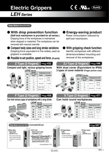 LEHZ
LEHZ67 Pages
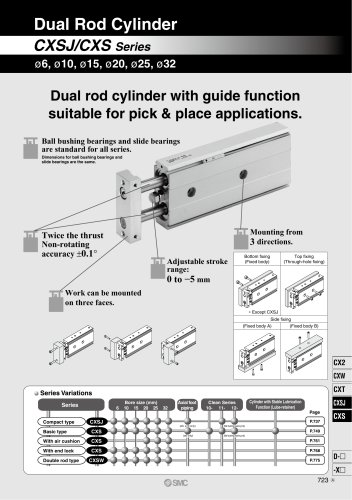 CXSJ
CXSJ60 Pages
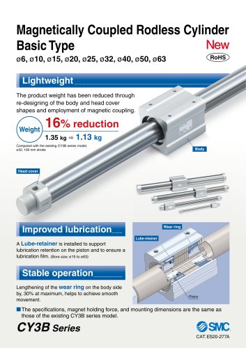 CY3B
CY3B17 Pages
 Aluminum High Vacuum Angle Valve
26 Pages
 AP Ultra High Purity
25 Pages
 IFW5 series
5 Pages
 Air Management System
64 Pages
 25A-ZSE20(F)/ISE20 Series
12 Pages
 ASG
ASG4 Pages
 IDG
IDG49 Pages
 CXSJ_M
2 Pages
 JLV20/30
8 Pages
 Series NCQ2/CQ2
252 Pages
 AC Series - Modular F.R.L. Units
70 Pages
 KQG2
KQG218 Pages
 IDF*E
IDF*E48 Pages
 AC10-A to AC40-A
82 Pages
 VQZ115, 100 Series
41 Pages
 SYJ300
60 Pages
 3000 Series
272 Pages
 MTS8
MTS823 Pages
 CXS-A
CXS-A60 Pages
 CXSL
CXSL60 Pages
 MXQR
MXQR36 Pages
 NC(D)Q2-Z
252 Pages
 MXH series
18 Pages
 KQ2
KQ2214 Pages
 Modular F.R.L. Units
108 Pages
 MXQ series
198 Pages
 Fieldbus System
92 Pages
 Fluoropolymer Piping Equipment
82 Pages
 Digital Flow Switch
24 Pages
 Vacuum Pad with Ejector
8 Pages
 Intrinsically safe Valve
43 Pages
 CQ2 series
25 Pages
 IDH, Thermo-dryer
12 Pages
 ISG
ISG10 Pages
 ISE3
ISE38 Pages
 ISE2
ISE27 Pages
 ISE1
ISE15 Pages
 ISA
ISA59 Pages
 IS3000
2 Pages
 IS10/10M/10E
4 Pages
 PSE series
44 Pages
 ISE70/75/75H
10 Pages
 ISE80
ISE8017 Pages
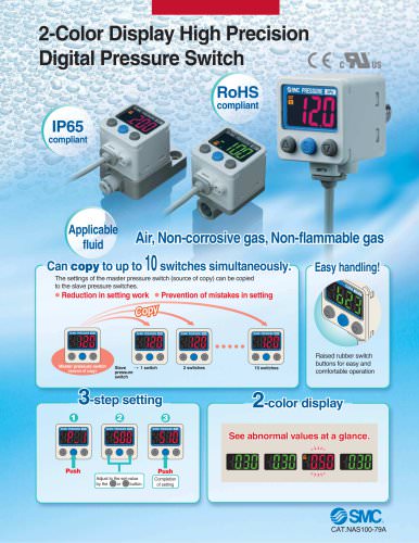 ISE40A
29 Pages
 HED series
16 Pages
 HEC series
32 Pages
 HEB series
9 Pages
 HRG series
85 Pages
 HRZ series
52 Pages
 HRW series
28 Pages
 LQ series
35 Pages
 LVQ series catalog
75 Pages
 PA series
37 Pages
 EX600, Analog Input/Output Unit
59 Pages
 LER series
62 Pages
 LEJ series
58 Pages
 ISE/ZSE30A series
18 Pages
 LAT3 series
24 Pages
 LEH series
103 Pages
 CQS series
59 Pages
 CH series
175 Pages
 ARX series
12 Pages
 HRS series
47 Pages
 LES
LES59 Pages
 MHS
MHS74 Pages
 MHY
MHY27 Pages
 MHC
MHC27 Pages
 MHR
MHR30 Pages
 MHZ series
78 Pages
 MSQ
MSQ37 Pages
 MGP
MGP127 Pages
 MXS
MXS38 Pages
 NRB
NRB10 Pages
 MXW
MXW22 Pages
 MHT
MHT11 Pages
 MY3
MY354 Pages
 CQM
CQM15 Pages
 NCA1
NCA163 Pages
 CM2
CM2152 Pages
 NCM
NCM91 Pages
 NCG
NCG96 Pages
 NCRA1
NCRA15 Pages
 CS2
CS232 Pages
 T/TIA
T/TIA1 Page
 KR
KR7 Pages
 KF
KF16 Pages
 KQ
KQ80 Pages
 AFF
AFF80 Pages
 AMG
AMG80 Pages
 IDF
IDF16 Pages
 HAA
HAA3 Pages
 ZFA
ZFA14 Pages
 ZA
ZA13 Pages
 MHF
MHF32 Pages
 CRB
CRB44 Pages
 D
D117 Pages
 RB
RB23 Pages
 CEP
CEP44 Pages
 rsq
rsq30 Pages
 CLK
CLK51 Pages
 MK
MK20 Pages
 CLJ
CLJ65 Pages
 MGJ
MGJ7 Pages
 ZSE30A
17 Pages
 IDFB*E
89 Pages
 ISE10
ISE1016 Pages
 ITV1000/2000
50 Pages
 AW
AW27 Pages
 NVFM200
12 Pages
 NVM100
32 Pages
 LLA*A
LLA*A36 Pages
 VX3*
VX3*41 Pages
 SY3000
158 Pages
 CH(D)2
175 Pages
 M(D)SUB
31 Pages


Archived catalogs
 Rodless cylinder
52 Pages
 ZSE1 series
12 Pages
 Rack and Pinion Rotary Actuators
37 Pages
 Special Fittings
14 Pages
 Toggle Grippers
16 Pages
 SX series
138 Pages
 ACG series
25 Pages
 C95 Pneumatic Cylinder
50 Pages
 Shock Absorber
16 Pages
 Silencer
4 Pages
 VV061 series
11 Pages
 Air Filter Catalog
18 Pages
 heavy Duty Actuators
88 Pages
 Self-seal Fittings Catalog
13 Pages
 Connectors Catalog
53 Pages

