- Products
- Catalogs
- News & Trends
- Exhibitions
ISA
1 /59Pages

ISA
1 /59Pages
Catalog excerpts

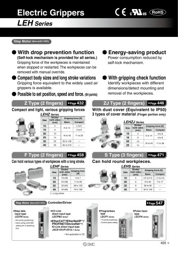
Air Catch Sensor Series ISA For Workpiece Placement Confirmation No-contact sensor for confirming workpiece placement, with a configuration that is less affected by supply pressure change. ZSP PS ISA PSE IS ISG ZSM Easy-to-set-up LED level meter Compliant with manifolds of up to 6 stations Proper set position is steadily and easily set due to the LED level meter and setting dial. Compliant with centralized wiring and piping Free mounting position Setting dial Stable detection is available at any mounting position due to the pressure sensor. Below set position (Green) Wide adjustment range Compliant between 10 and 300 μm Stably detects 10 μm clearance The configuration is unlikely to be affected by supply pressure change due to the air pressure bridge circuit and semi-conductor pressure sensor. Dustproof and dripproof type
Open the catalog to page 1
Individual wiring/Centralized wiring PNP open collector output With bracket NPT open collector output Output specifications With gauge ∗ DIN rail must be ordered separately. Wiring specifications Ex. 1) NPN output, 4 stations, centralized wiring terminal block BOX (left), with bracket and gauge Individual wiring (Without terminal block BOX) Centralized wiring (With terminal block BOX, left side) Centralized wiring (With terminal block BOX, right side) Ex. 2) PNP output, individual wiring, with gauge Accessory · Bracket: ISA-1-A · Gauge: G33-3-01 · DIN rail: ISA-2-1 to 7 · DIN rail: ISA-2-1 to...
Open the catalog to page 2
Series ISA Specifications Dry air (filtered to 5 μm) Fluid Operating pressure range Recommended pressure range Detection distance range Repeatability including temperature characteristics ±10 μm (0 to 60°C (standard 25°C)) 10 μm or less (Detection distance: 10 to 150 μm) Hysteresis Detection nozzle O.D. ø1.0 standard (Refer to page 820 for data when the nozzle diameter is modified.) Display function Operating indicator light (Lights ON), Deviation level indicator light Power supply voltage 12 to 24 VDC ±10%, Ripple (p-p) 10% or less (With power supply polarity protection) Current consumption...
Open the catalog to page 3
Internal Circuit and Wiring Centralized wiring type NPN-type open collector Refer to the below figure for the relation between terminal block wiring in terminal box and switch. Main circuit of switch PNP-type open collector Main circuit of switch Specific Product Precautions Read before handling. Refer to front matters 58 and 59 for Safety Instructions and pages 687 to 691 for Pressure Switch Precautions. Operating Environment Caution 1. If the detection nozzle is exposed to splashes of water or cutting oil, do not allow backflow from the detection nozzle to the switch body. Install the switch...
Open the catalog to page 4
Series ISA Dimensions: Centralized Wiring Type (Terminal Block Box Type) Setting dial Lead wire electrical entry Applicable O.D.ø6.5 to ø8.5 Gauge Lead wire electrical entry Applicable O.D ø6.5 to ø8.5 Manifold Deviation level indicator light When the bracket has two stations and the terminal block box is on the right side, it attaches to the second switch, while when it is on the left side, it attaches to the first switch. With n stations, it attaches to the first switch and the nth switch. Deviation level indicator light Terminal block box wiring diagram Lead wire electrical entry Applicable...
Open the catalog to page 5
Dimensions: Individual Wiring Type (Lead Wire Type) Body With bracket Manifold Lead wire (5 m) SUP port Rc 1/8 DIN rail center Deviation level indicator light 90 100 Deviation level indicator light Gauge When the bracket has two stations, it attaches to the first switch. With n stations, it attaches to the first switch and the nth switch. Setting dial Deviation level indicator light SUP port Rc 1/8 DIN rail center 40 30 (4.5) Deviation level indicator light 25 Dimensions: With DIN rail Station
Open the catalog to page 6
Series ISA Operation guideline: Design data When you design the pneumatic circuit using the air catch sensor, please refer to the data below. The detection distance of the air catch sensor is between 10 and 300 μm. However, please note that stable detection cannot be done when supply pressure or nozzle size are different. Relation between Nozzle Diameter and Detection Distance The data in the following charts are characteristics of hysteresis at the detection distance. In case accuracy is required by the settings, the design should be made so that the hysteresis will stay within the optimum adjustment...
Open the catalog to page 7
Response Time Response time changes with detection distance and piping length. It is hardly influenced by the supply pressure and nozzle diameter (ø1.0 to ø2.0). While both graphs assume a fixed set distance with changes in the detection distance, Fig. 2 shows responses at various set values and Fig. 3 shows responses at various piping lengths. If the detection distance is equal to the set value, the response becomes quicker as the set value becomes smaller or the piping length becomes shorter. Detection nozzle: ø1.0 Operating piping: ø6 x ø4 tubing Supply pressure: 0.1 MPa Set distance: 100...
Open the catalog to page 8
Air Catch Sensor Series ISA2 Non-Contact Sensor for Workpiece Placement Confirmation Due to the pneumatic bridge circuit and semiconductor pressure sensor, the non-contact type sensor is hardly affected by fluctuations in the supply pressure. Plug connectors (Centralized wiring) Modular construction Requires less man hours to wire. Easy to add and remove manifold stations. Requires less man hours to wire. With regulator + 2 port solenoid valve With 2 port solenoid valve PSE IS ISG Optimum position is known at a glance. LED level meter large dial Above set position Below set position Green Extraneous...
Open the catalog to page 9
Series ISA2 How to Order Manifold Without control unit With control unit E2 Pressure gauge of regulator Note 1) Without pressure gauge Note 2) A* E2 MPa single notation 0.2 Square embedded pressure gauge Z2* psi single notation MPa E4 MPa single notation 0.4 Z4* psi single notation MPa G2 MPa single notation 0.2 Round pressure gauge P2* MPa-psi double notation MPa G4 MPa single notation 0.4 P4* MPa-psi double notation MPa With regulator + 2 port solenoid valve With 2 port solenoid valve Electrical entry and supply port position SR SL PR PL Note 1) Due to new Japanese weight and measurement legislation,...
Open the catalog to page 10All SMC Corporation of America catalogs and technical brochures
 LEHZ
LEHZ67 Pages
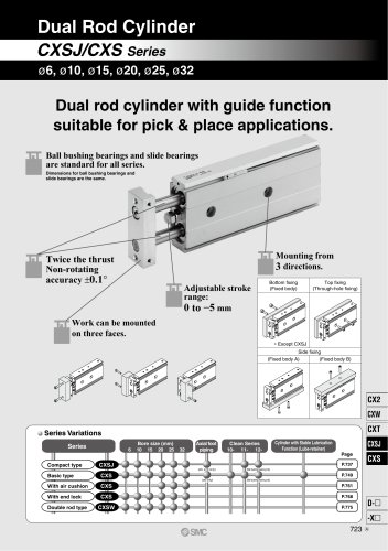 CXSJ
CXSJ60 Pages
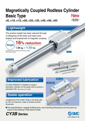 CY3B
CY3B17 Pages
 Aluminum High Vacuum Angle Valve
26 Pages
 AP Ultra High Purity
25 Pages
 IFW5 series
5 Pages
 Air Management System
64 Pages
 25A-ZSE20(F)/ISE20 Series
12 Pages
 ASG
ASG4 Pages
 IDG
IDG49 Pages
 CXSJ_M
2 Pages
 JLV20/30
8 Pages
 Series NCQ2/CQ2
252 Pages
 AC Series - Modular F.R.L. Units
70 Pages
 KQG2
KQG218 Pages
 IDF*E
IDF*E48 Pages
 AC10-A to AC40-A
82 Pages
 VQZ115, 100 Series
41 Pages
 SYJ300
60 Pages
 3000 Series
272 Pages
 MTS8
MTS823 Pages
 CXS-A
CXS-A60 Pages
 CXSL
CXSL60 Pages
 MXQR
MXQR36 Pages
 NC(D)Q2-Z
252 Pages
 LEY series
88 Pages
 MXH series
18 Pages
 KQ2
KQ2214 Pages
 Modular F.R.L. Units
108 Pages
 MXQ series
198 Pages
 Fieldbus System
92 Pages
 Fluoropolymer Piping Equipment
82 Pages
 Digital Flow Switch
24 Pages
 Vacuum Pad with Ejector
8 Pages
 Intrinsically safe Valve
43 Pages
 CQ2 series
25 Pages
 IDH, Thermo-dryer
12 Pages
 ISG
ISG10 Pages
 ISE3
ISE38 Pages
 ISE2
ISE27 Pages
 ISE1
ISE15 Pages
 IS3000
2 Pages
 IS10/10M/10E
4 Pages
 PSE series
44 Pages
 ISE70/75/75H
10 Pages
 ISE80
ISE8017 Pages
 ISE40A
29 Pages
 HED series
16 Pages
 HEC series
32 Pages
 HEB series
9 Pages
 HRG series
85 Pages
 HRZ series
52 Pages
 HRW series
28 Pages
 LQ series
35 Pages
 LVQ series catalog
75 Pages
 PA series
37 Pages
 EX600, Analog Input/Output Unit
59 Pages
 LER series
62 Pages
 LEJ series
58 Pages
 ISE/ZSE30A series
18 Pages
 LAT3 series
24 Pages
 LEH series
103 Pages
 CQS series
59 Pages
 CH series
175 Pages
 ARX series
12 Pages
 HRS series
47 Pages
 LES
LES59 Pages
 MHS
MHS74 Pages
 MHY
MHY27 Pages
 MHC
MHC27 Pages
 MHR
MHR30 Pages
 MHZ series
78 Pages
 MSQ
MSQ37 Pages
 MGP
MGP127 Pages
 MXS
MXS38 Pages
 NRB
NRB10 Pages
 MXW
MXW22 Pages
 MHT
MHT11 Pages
 MY3
MY354 Pages
 CQM
CQM15 Pages
 NCA1
NCA163 Pages
 CM2
CM2152 Pages
 NCM
NCM91 Pages
 NCG
NCG96 Pages
 NCRA1
NCRA15 Pages
 CS2
CS232 Pages
 T/TIA
T/TIA1 Page
 KR
KR7 Pages
 KF
KF16 Pages
 KQ
KQ80 Pages
 AFF
AFF80 Pages
 AMG
AMG80 Pages
 IDF
IDF16 Pages
 HAA
HAA3 Pages
 ZFA
ZFA14 Pages
 ZA
ZA13 Pages
 MHF
MHF32 Pages
 CRB
CRB44 Pages
 D
D117 Pages
 RB
RB23 Pages
 CEP
CEP44 Pages
 rsq
rsq30 Pages
 CLK
CLK51 Pages
 MK
MK20 Pages
 CLJ
CLJ65 Pages
 MGJ
MGJ7 Pages
 ZSE30A
17 Pages
 IDFB*E
89 Pages
 ISE10
ISE1016 Pages
 ITV1000/2000
50 Pages
 AW
AW27 Pages
 NVFM200
12 Pages
 NVM100
32 Pages
 LLA*A
LLA*A36 Pages
 VX3*
VX3*41 Pages
 SY3000
158 Pages
 CH(D)2
175 Pages
 M(D)SUB
31 Pages


Archived catalogs
 Rodless cylinder
52 Pages
 ZSE1 series
12 Pages
 Rack and Pinion Rotary Actuators
37 Pages
 Special Fittings
14 Pages
 Toggle Grippers
16 Pages
 SX series
138 Pages
 ACG series
25 Pages
 C95 Pneumatic Cylinder
50 Pages
 Shock Absorber
16 Pages
 Silencer
4 Pages
 VV061 series
11 Pages
 Air Filter Catalog
18 Pages
 heavy Duty Actuators
88 Pages
 Self-seal Fittings Catalog
13 Pages
 Connectors Catalog
53 Pages

