- Catalogs
- SMC Corporation of America
- HRG series
HRG series
1 /85Pages

HRG series
1 /85Pages
Catalog excerpts

Circulating Fluid Temperature Controller Refrigerated Thermo-cooler Series HRG 1.1kW / 2.3 kW / 4.8 kW, 9.5 kW / 14.5 kW 1.1kW / 2.3 kW / 4.8 kW, 11.0 kW / 16.5 kW Temperature stability: +1 / +0.5°C – °C – Temperature range setting: 5 to 35°C (Air-cooled refrigeration) Makes cooling water easily available, anytime, anywhere. (Proportional valve PID control) Temperature control of LCD panels Example: Cooling an LCD panel Temperature control of welding torches Related Products Application Examples Can be used in many applications other than those shown below. Refer to “Application Examples” section of this catalog. As a replacement for a cooling tower Example: Laser welding Cooling plate With casters (Option) Can be used for cooling during transfer to processing, before and after resist coating and firing of the glass substrate. Can be used to supply cooling water to welding torches or commercially available laser welding devices, and to prevent overheating of the torch or the oscillation tube. Technical Data (Refrigerator ON/OFF control) (Water-cooled refrigeration) Installing extra cooling towers can be troublesome. The HRG series (air-cooled refrigeration) can be moved easily to wherever you need it, when you need it. Cooling water is supplied from the attached hose.
Open the catalog to page 1
Energy Saving Power consumption: Max. When the circulating fluid reaches a certain preset temperature, the refrigerator stops temporarily (idling stop) and the temperature is adjusted (refrigerator ON/OFF control). Stopping the refrigerator for longer periods of time and operating at low load (idling mode) reduces power consumption dramatically. Even in processes where there is heat loading, performance is at least as good as that of inverter control. Idling mode Note): 1.45 kW Process mode: 1.45 kW Inverter control Refrigerator ON/OFF control (HRG002-A) Note) Operating conditions: Process mode:...
Open the catalog to page 2
Space Saving External volume: Max. 23% reduction Footprint: Max.12% reduction (SMC comparison) Conventional model Improvements in the HRG’s high-performance heat exchanger have enabled the size of the unit to be reduced, with corresponding reductions in mass and space needed for installation. Install directly against the wall for further reduction in installation space Thermo-cooler (Air-cooled refrigeration) Ventilation Ventilation Space saving Cooling capacity: • Aqueous solution of 15% ethylene glycol • Clear water, Deionized water Note) A maximum cooling capacity of 16.5 kW has been achieved...
Open the catalog to page 3
Easy Operation and Maintenance Simple operation With individual alarm indicators (Standard specifications) Three separate levels of alarm indicators Note) for easy faiure diagnosis. Operation 1 Press the ON button. (Supplied as standard for the HRG010- and HRG015-, and as specials for the HRG001 to HRG005.) Adjust the temperature setting with the UP/DOWN keys. Individual red LED alarm indicators ALARM1 Operation 3 Press the OFF button to shut down. What could be easier?! Water delivery circuit error Abnormal installation status Refrigeration circuit error Note) Refer to page 24 for operation...
Open the catalog to page 4
Application Examples Semiconductor Medical Example: Blood preservation Example: Temperature control of a chamber electrode Upper electrode Lower electrode • X-ray instrument • MRI • Blood preservation equipment • Etching equipment • Coating equipment • Spatter equipment • Dicing equipment • Cleaning equipment • Tester, etc. Example: Electronic microscope Example: Tofu (Bean curd) production Electronic microscope • Electron microscope • X-ray analytical instrument • Gas chromatography • Sugar level analytical instrument, etc. Machine tool Prevents the distortion caused by the heat generated by...
Open the catalog to page 5
Construction and Principles HRG-A (Air-cooled refrigeration) (Water-cooled refrigeration) Air-cooled condenser Refrigerant circuit High-pressure shutdown switch Facility water inlet HRG001 to 005-5 (Temperature stability: ±0.5°C type) Automatic water supply function Tank Overflow Refrigerant dryer Water control valve Capillary tube or expansion valve Fluid level gauge Water-cooled condenser Level switch Evaporator (cooler) Facility water outlet Circulating fluid circuit Temperature sensor Facility water circuit Solenoid valve Circulating fluid outlet By-pass valve Volume adjustment valve Proportional...
Open the catalog to page 6
Model Selection Property Values Basic Model Facility Water Required Flow Rate • Optional Accessories
Open the catalog to page 7
Model Selection Guide to Model Selection 1. Which is best for you: a water-cooled refrigeration or an air-cooled refrigeration? You should base your choice on the configuration of your equipment. Thermo-cooler series refrigeration methods Water-cooled refrigeration Requires facility water equipment (cooling tower etc.) as well as electrical power supply. This type provides stable cooling performance year round, regardless of ambient temperature changes. Air-cooled refrigeration Only electrical power supply is needed. Facility water equipment is not necessary, so the system is easy to install...
Open the catalog to page 8
Model Selection Cooling method : Air-cooled refrigeration Circulating fluid temperature: 20°C Fluid : Clear water Power supply frequency : 60 Hz Required cooling capacity : 4.2 kW Example: Customer requirements 1 to 5 Based on the results of 1 to 5, refer to the graph of cooling capacity of an air-cooled refrigeration Thermo-cooler at 60 Hz (page 16). On the same graph, plot the intersections between the customer’s required temperature (20°C) and cooling capacity (4.2 kW). Refer to the same graph that can be used for ethylene glycol aqueous solution (15% or less.) [Cooling Capacity Graph] Cooling...
Open the catalog to page 9
Model Selection Calculation of Required Cooling Capacity Example 1: When the heat generation amount in the customer's equipment is known. The heat generation amount can be determined based on the power consumption or output of the heat generating area — i.e. the area requiring cooling — within your facility.∗ (1) Derive the amount of heat generated from the power consumption. Power consumption P: 3.5 [kW] Q = P = 3.5 [kW] Cooling capacity = Considering a safety factor of 20%, 3.5 [kW] x 1.2 = 4.2 [kW] I: Current V: Power supply voltage P (2) Derive the amount of heat generated from the power...
Open the catalog to page 10All SMC Corporation of America catalogs and technical brochures
 LEHZ
LEHZ67 Pages
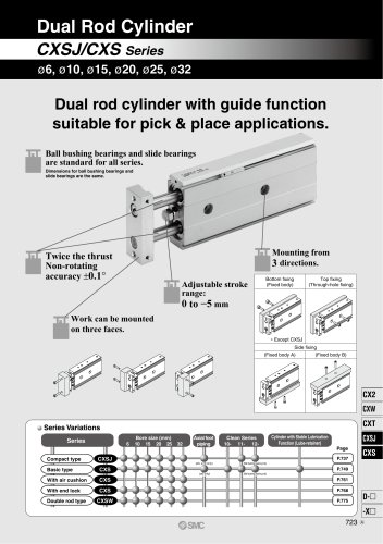 CXSJ
CXSJ60 Pages
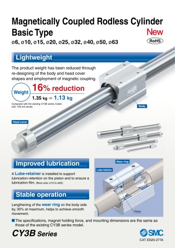 CY3B
CY3B17 Pages
 Aluminum High Vacuum Angle Valve
26 Pages
 AP Ultra High Purity
25 Pages
 IFW5 series
5 Pages
 Air Management System
64 Pages
 25A-ZSE20(F)/ISE20 Series
12 Pages
 ASG
ASG4 Pages
 IDG
IDG49 Pages
 CXSJ_M
2 Pages
 JLV20/30
8 Pages
 Series NCQ2/CQ2
252 Pages
 AC Series - Modular F.R.L. Units
70 Pages
 KQG2
KQG218 Pages
 IDF*E
IDF*E48 Pages
 AC10-A to AC40-A
82 Pages
 VQZ115, 100 Series
41 Pages
 SYJ300
60 Pages
 3000 Series
272 Pages
 MTS8
MTS823 Pages
 CXS-A
CXS-A60 Pages
 CXSL
CXSL60 Pages
 MXQR
MXQR36 Pages
 NC(D)Q2-Z
252 Pages
 LEY series
88 Pages
 MXH series
18 Pages
 KQ2
KQ2214 Pages
 Modular F.R.L. Units
108 Pages
 MXQ series
198 Pages
 Fieldbus System
92 Pages
 Fluoropolymer Piping Equipment
82 Pages
 Digital Flow Switch
24 Pages
 Vacuum Pad with Ejector
8 Pages
 Intrinsically safe Valve
43 Pages
 CQ2 series
25 Pages
 IDH, Thermo-dryer
12 Pages
 ISG
ISG10 Pages
 ISE3
ISE38 Pages
 ISE2
ISE27 Pages
 ISE1
ISE15 Pages
 ISA
ISA59 Pages
 IS3000
2 Pages
 IS10/10M/10E
4 Pages
 PSE series
44 Pages
 ISE70/75/75H
10 Pages
 ISE80
ISE8017 Pages
 ISE40A
29 Pages
 HED series
16 Pages
 HEC series
32 Pages
 HEB series
9 Pages
 HRZ series
52 Pages
 HRW series
28 Pages
 LQ series
35 Pages
 LVQ series catalog
75 Pages
 PA series
37 Pages
 EX600, Analog Input/Output Unit
59 Pages
 LER series
62 Pages
 LEJ series
58 Pages
 ISE/ZSE30A series
18 Pages
 LAT3 series
24 Pages
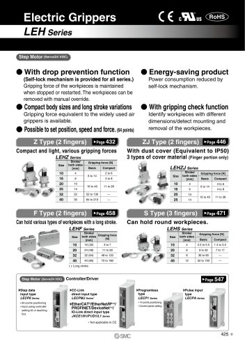
 LEH series
103 Pages
 CQS series
59 Pages
 CH series
175 Pages
 ARX series
12 Pages
 HRS series
47 Pages
 LES
LES59 Pages
 MHS
MHS74 Pages
 MHY
MHY27 Pages
 MHC
MHC27 Pages
 MHR
MHR30 Pages
 MHZ series
78 Pages
 MSQ
MSQ37 Pages
 MGP
MGP127 Pages
 MXS
MXS38 Pages
 NRB
NRB10 Pages
 MXW
MXW22 Pages
 MHT
MHT11 Pages
 MY3
MY354 Pages
 CQM
CQM15 Pages
 NCA1
NCA163 Pages
 CM2
CM2152 Pages
 NCM
NCM91 Pages
 NCG
NCG96 Pages
 NCRA1
NCRA15 Pages
 CS2
CS232 Pages
 T/TIA
T/TIA1 Page
 KR
KR7 Pages
 KF
KF16 Pages
 KQ
KQ80 Pages
 AFF
AFF80 Pages
 AMG
AMG80 Pages
 IDF
IDF16 Pages
 HAA
HAA3 Pages
 ZFA
ZFA14 Pages
 ZA
ZA13 Pages
 MHF
MHF32 Pages
 CRB
CRB44 Pages
 D
D117 Pages
 RB
RB23 Pages
 CEP
CEP44 Pages
 rsq
rsq30 Pages
 CLK
CLK51 Pages
 MK
MK20 Pages
 CLJ
CLJ65 Pages
 MGJ
MGJ7 Pages
 ZSE30A
17 Pages
 IDFB*E
89 Pages
 ISE10
ISE1016 Pages
 ITV1000/2000
50 Pages
 AW
AW27 Pages
 NVFM200
12 Pages
 NVM100
32 Pages
 LLA*A
LLA*A36 Pages
 VX3*
VX3*41 Pages
 SY3000
158 Pages
 CH(D)2
175 Pages
 M(D)SUB
31 Pages


Archived catalogs
 Rodless cylinder
52 Pages
 ZSE1 series
12 Pages
 Rack and Pinion Rotary Actuators
37 Pages
 Special Fittings
14 Pages
 Toggle Grippers
16 Pages
 SX series
138 Pages
 ACG series
25 Pages
 C95 Pneumatic Cylinder
50 Pages
 Shock Absorber
16 Pages
 Silencer
4 Pages
 VV061 series
11 Pages
 Air Filter Catalog
18 Pages
 heavy Duty Actuators
88 Pages
 Self-seal Fittings Catalog
13 Pages
 Connectors Catalog
53 Pages

