CY3B
1 /17Pages
CY3B
1 /17Pages
Catalog excerpts
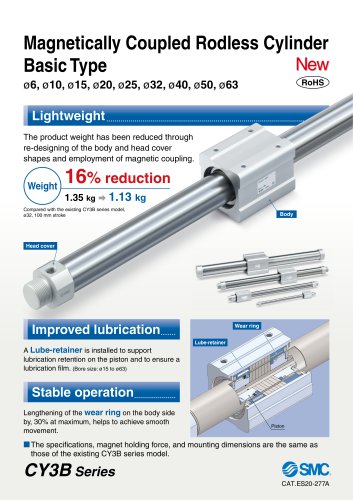
Magnetically Coupled Rodless Cylinder Basic Type RoHS Lightweight The product weight has been reduced through re-designing of the body and head cover shapes and employment of magnetic coupling. Compared with the existing CY3B series model, ø32, 100 mm stroke Head cover Improved lubrication A Lube-retainer is installed to support lubrication retention on the piston and to ensure a lubrication film. (Bore size: ø15 to ø63) Wear ring Lube-retainer Stable operation Lengthening of the wear ring on the body side by, 30% at maximum, helps to achieve smooth movement. M The specifications, magnet holding force, and mounting dimensions are the same as those of the existing CY3B series model.
Open the catalog to page 1
Cushion . * holding
Open the catalog to page 2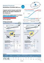
Related Products tions: 700,000 varialications models and 12,000 basicduct variations to accommodate various app Click here for details Deceleration Controller DAS Series Cushion intensity adjustment 2-speed control reduces cycle time Allows for the impact relaxation of the stroke end Cushion timing adjustment Allows for the 2-speed control of cylinders The deceleration position (cushion timing) and 2nd speed (cushion intensity) Operating time M Piping Example For double-end Deceleration after high-speed driving Deceleration after high-speed driving Deceleration Controller Deceleration Controller...
Open the catalog to page 3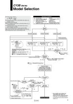
Model Selection E: Kinetic energy of load [J] (W + WB) V 2 E= x 2 1000 Es: Allowable kinetic energy for intermediate stop using an air pressure circuit [J] Fn: Allowable driving force [N] MD: Max. allowable moment when a connection bracket, etc., is carried directly [N⋅m] Ps: Operating pressure limit for intermediate stop using an external stopper, etc. [MPa] Pv: Max. operating pressure for vertical operation [MPa] WBmax: Max. load mass when loaded directly on the body [kg] Wv: Allowable load mass for vertical operation [kg] Operating Conditions /Switches Load mass [kg] /P: Operating pressure...
Open the catalog to page 5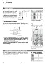
* Use caution, as there is a danger of breaking the magnetic coupling if operated above the max. operating pressure. CY3B Series1 Vertical Operation It is recommended that the load is guided by a ball type bearing (linear guide, etc.). If a slide bearing is used, sliding resistance increases due to the load mass and moment, which may cause malfunctions. When the cylinder is mounted vertically or on an angle, be sure to use an external stopper, etc., for positioning. In addition, as the slider may move downward toward the stroke end due to its self-weight or the mass of the workpiece, use an external...
Open the catalog to page 6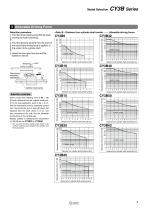
3 Allowable Driving Force <Data A : Distance from cylinder shaft center-Allowable driving force> Usable range 0123456789 10 11 Distance from cylinder shaft center Lo [cm] Selection procedure1. Find the drive resisting force Fn [N] when J moving the load horizontally.2. Find the distance Lo [cm] from the point of (the load where driving force is applied, to the center of the cylinder shaft. Given a load drive resisting force of Fn = 100 [N] and a distance from the cylinder shaft center to the load application point of Lo = 8 cm, find the intersection point by extending upward from the horizontal...
Open the catalog to page 7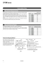
Intermediate Stop4 Stop with Air Pressure Circuit When performing an intermediate stop of a load using an air pressure circuit, operate at or below the kinetic energy shown in the table on the right. Use caution, as operation when exceeding the allowable value can result in breaking of the magnetic coupling. When the cylinder is operated at full stroke without an external stopper, a similar condition may result. Therefore, use the product with the kinetic energy shown in the table on the right or below. When an intermediate stop is performed by means of an air pressure circuit, the body stopping...
Open the catalog to page 8
Magnetically Coupled Rodless Cylinder Basic Type Basic type Basic typed Bore size* 6 Standard stroke Refer to the standard stroke table shown below. • Port thread type Symbol Standard Strokes Symbol Rubber bumper (Magnet type) Click here for details *1 Note that to perform an intermediate stop with an external stopper, the required operating pressure limit is the pressure explained in “Stop with External Stopper” on page 5.
Open the catalog to page 9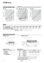
ACaution When calculating the actual thrust, design should consider the min. operating pressure. Replacement Parts: Seal Kit CY3B6, 10-DZ Component Parts Seal Kit/Part Nos. * As sizes 050 and 063 cannot be disassembled, the seal kit cannot be replaced. * The seal kit includes a grease pack (10 g). Order with the following part number when only the grease pack is required. Grease pack part number: GR-S-010 * For bore size 010, wear ring A cannot be replaced.
Open the catalog to page 10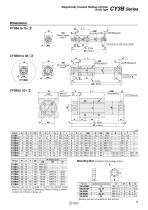
Magnetically Coupled Rodless Cylinder * Mounting nuts are not available for 050 and 063.
Open the catalog to page 11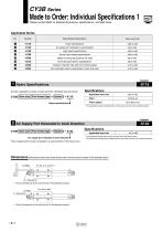
Please contact SMC for detailed dimensions, specifications, and lead times. This type is applicable for precision constant speed feed, intermediate stop and skip feed. CY3B Bore size Port thread type — Stroke Z — X116 Hydro specifications« Specifications Applicable bore size * The applicable strokes and dimensions are the same as those of the standard product. Dimensions (Dimensions other than those shown below are the same as those of the standard type.)
Open the catalog to page 12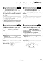
CY3B Bore size Port thread type — Stroke Z — X160 High speed specifications! This makes a high speed piston drive of 1500 mm/s possible (without load), but it is not applicable for all conditions. Contact SMC for the operating conditions, etc. Port thread type Z — X168 Helical insert thread specifications« A product with a helical insert thread that allows for increased mounting screw strength Specifications__ Specifications * When operating this cylinder at a speed which exceeds the range of the standard product * The applicable strokes and dimensions are the same as those of the standard product....
Open the catalog to page 13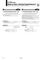
Please contact SMC for detailed dimensions, specifications, and lead times. CY3B Bore size Port thread type Stroke Z-X322 Outside of cylinder tube with hard chrome plated The cylinder tube outer circumference is plated with hard chrome, which further reduces bearing abrasion. * The maximum stroke is 3500 st, or the maximum stroke for the standard type. CY3B Bore size Port thread type — Stroke Z— X324 Non-lubricated exterior specifications (with dust seal) 1 No grease is applied to the external surface of the cylinder. It is recommended to use this type in a special environment where standard...
Open the catalog to page 14All SMC Corporation of America catalogs and technical brochures
 LEHZ
LEHZ67 Pages
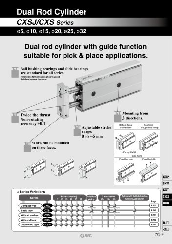 CXSJ
CXSJ60 Pages
 Aluminum High Vacuum Angle Valve
26 Pages
 AP Ultra High Purity
25 Pages
 IFW5 series
5 Pages
 Air Management System
64 Pages
 25A-ZSE20(F)/ISE20 Series
12 Pages
 ASG
ASG4 Pages
 IDG
IDG49 Pages
 CXSJ_M
2 Pages
 JLV20/30
8 Pages
 Series NCQ2/CQ2
252 Pages
 AC Series - Modular F.R.L. Units
70 Pages
 KQG2
KQG218 Pages
 IDF*E
IDF*E48 Pages
 AC10-A to AC40-A
82 Pages
 VQZ115, 100 Series
41 Pages
 SYJ300
60 Pages
 3000 Series
272 Pages
 MTS8
MTS823 Pages
 CXS-A
CXS-A60 Pages
 CXSL
CXSL60 Pages
 MXQR
MXQR36 Pages
 NC(D)Q2-Z
252 Pages
 LEY series
88 Pages
 MXH series
18 Pages
 KQ2
KQ2214 Pages
 Modular F.R.L. Units
108 Pages
 MXQ series
198 Pages
 Fieldbus System
92 Pages
 Fluoropolymer Piping Equipment
82 Pages
 Digital Flow Switch
24 Pages
 Vacuum Pad with Ejector
8 Pages
 Intrinsically safe Valve
43 Pages
 CQ2 series
25 Pages
 IDH, Thermo-dryer
12 Pages
 ISG
ISG10 Pages
 ISE3
ISE38 Pages
 ISE2
ISE27 Pages
 ISE1
ISE15 Pages
 ISA
ISA59 Pages
 IS3000
2 Pages
 IS10/10M/10E
4 Pages
 PSE series
44 Pages
 ISE70/75/75H
10 Pages
 ISE80
ISE8017 Pages
 ISE40A
29 Pages
 HED series
16 Pages
 HEC series
32 Pages
 HEB series
9 Pages
 HRG series
85 Pages
 HRZ series
52 Pages
 HRW series
28 Pages
 LQ series
35 Pages
 LVQ series catalog
75 Pages
 PA series
37 Pages
 EX600, Analog Input/Output Unit
59 Pages
 LER series
62 Pages
 LEJ series
58 Pages
 ISE/ZSE30A series
18 Pages
 LAT3 series
24 Pages
 LEH series
103 Pages
 CQS series
59 Pages
 CH series
175 Pages
 ARX series
12 Pages
 HRS series
47 Pages
 LES
LES59 Pages
 MHS
MHS74 Pages
 MHY
MHY27 Pages
 MHC
MHC27 Pages
 MHR
MHR30 Pages
 MHZ series
78 Pages
 MSQ
MSQ37 Pages
 MGP
MGP127 Pages
 MXS
MXS38 Pages
 NRB
NRB10 Pages
 MXW
MXW22 Pages
 MHT
MHT11 Pages
 MY3
MY354 Pages
 CQM
CQM15 Pages
 NCA1
NCA163 Pages
 CM2
CM2152 Pages
 NCM
NCM91 Pages
 NCG
NCG96 Pages
 NCRA1
NCRA15 Pages
 CS2
CS232 Pages
 T/TIA
T/TIA1 Page
 KR
KR7 Pages
 KF
KF16 Pages
 KQ
KQ80 Pages
 AFF
AFF80 Pages
 AMG
AMG80 Pages
 IDF
IDF16 Pages
 HAA
HAA3 Pages
 ZFA
ZFA14 Pages
 ZA
ZA13 Pages
 MHF
MHF32 Pages
 CRB
CRB44 Pages
 D
D117 Pages
 RB
RB23 Pages
 CEP
CEP44 Pages
 rsq
rsq30 Pages
 CLK
CLK51 Pages
 MK
MK20 Pages
 CLJ
CLJ65 Pages
 MGJ
MGJ7 Pages
 ZSE30A
17 Pages
 IDFB*E
89 Pages
 ISE10
ISE1016 Pages
 ITV1000/2000
50 Pages
 AW
AW27 Pages
 NVFM200
12 Pages
 NVM100
32 Pages
 LLA*A
LLA*A36 Pages
 VX3*
VX3*41 Pages
 SY3000
158 Pages
 CH(D)2
175 Pages
 M(D)SUB
31 Pages


Archived catalogs
 Rodless cylinder
52 Pages
 ZSE1 series
12 Pages
 Rack and Pinion Rotary Actuators
37 Pages
 Special Fittings
14 Pages
 Toggle Grippers
16 Pages
 SX series
138 Pages
 ACG series
25 Pages
 C95 Pneumatic Cylinder
50 Pages
 Shock Absorber
16 Pages
 Silencer
4 Pages
 VV061 series
11 Pages
 Air Filter Catalog
18 Pages
 heavy Duty Actuators
88 Pages
 Self-seal Fittings Catalog
13 Pages
 Connectors Catalog
53 Pages

