- Products
- Catalogs
- News & Trends
- Exhibitions
CS2
1 /32Pages

CS2
1 /32Pages
Catalog excerpts

Air Cylinder New Large Bore Sizes ø125, ø140, ø160 Lighter installation achieved by reducing weight. Ȝ Die cast rod cover and head cover used to achieve greater weight reduction. Ȝ Rod bore size changed to suit uses, achieving greater weight reduction. Ȝ Weight 27.2 kg Reduced by Max. 58% CS1 CS2 Weight Comparison (Basic Type ø160-100st) 35 Weight (kg) 30 11.3 kg 25 30.1 27.2 57% Reduction 58% 20 Reduction 15 10 13.1 11.3 5 0 CS1 CS2 Standard CS1 CS1W CS2W Double Rod Type CS2 Standard Series Expanded NEW Maximum stroke when using rotating bracket Expanded by 1.6 times (compared to series CS1) Double Rod Type, Smooth Cylinder Lighter cylinder reduces self-weight deflection. Stroke range extended to widen use. 9 Made to Order types added! added to Series CS2! Maximum allowable stroke when using clevis bracket 1.6 times Stroke (mm) 1,500 CS2 CS1 CS2 650 410 CS1 500 Mounting angle 0 0 15 30 45 60 75 Mounting angle (DEG.) 90 Double Rod Type Allowable lateral load of CS1 and CS2 Series CS1 Even if rod diameter is changed to suit various needs, function remains equal to Series CS1. Allowable lateral load (N) Allowable lateral load equal to Series Mounting angle 45° 1,200 1,000 400 300 160 200 100 0 125&140 0 400 800 1200 Stroke (mm) 1600 Smooth Cylinder Series CS2 CAT.ES20-196B
Open the catalog to page 1
Air Cylinder Series CS2 Compact auto switches can be mounted Improved operability after installation 2-color display auto switches can be mounted, enabling precise determination of mounting position, without error. Operability has been improved by placing the piping port and cushion valve operation position on the same side. Interchangeability with Series CS1 Cushion seals are now replaceable Cylinder mounting dimensions and rod end thread sizes are interchangeable with Series CS1. Smooth Cylinder Maintenance improved by making cushion seals replaceable. Ȝ Minimum operating pressure 0.005 MPa...
Open the catalog to page 2
Combination of Standard Products and Made to Order Specifications Made to Order specifications Special product (Contact SMC for details) Double acting (Smooth Cylinder) Double acting
Open the catalog to page 3
Air Cylinder Series CS2 ø125, ø140, ø160 How to Order CS2 L 125 CDS2 L 125 With auto switch 300 300 M9BW With auto switch (Built-in magnet) Made to Order For details, refer to the next page. Mounting B L F G C D T Number of auto switches Basic Foot Rod flange Head flange Single clevis Double clevis Center trunnion Nil 3 S n Auto switch Without auto switch Nil ∗ Refer to the table below for the applicable auto switch model. Bore size 125 140 160 125 mm 140 mm 160 mm Suffix for cylinder Nil Built-in Magnet Cylinder Model If a built-in magnet cylinder without auto switch is required, there is no...
Open the catalog to page 4
Air Cylinder Series CS2 Specifications Bore size (mm) 125 140 Action 160 Double acting, Single rod Air Proof pressure 1.57 MPa Maximum operating pressure 0.97 MPa Minimum operating pressure 0.05 MPa Piston speed 50 to 500 mm/s Cushion Air cushion 0 to 70°C (No freezing) With auto switch 0 to 60°C (No freezing) Double acting Lubrication Not required (Non-lube) Stroke Tolerance 250 or less +1.0 0 251 to 1000 +1.4 0 1001 to 1500 +1.8 0 1501 to 1600 +2.2 0 Stroke length tolerance (mm) Made to Order Specifications (For details, refer to pages 25 to 29.) Symbol Basic, Foot, Rod flange, Head flange,...
Open the catalog to page 5
Series CS2 Weight (kg) Bore size (mm) 140 160 Basic 5.46 6.50 9.07 Foot 7.49 9.50 12.45 Rod flange 8.51 12.03 15.80 Head flange 8.51 12.03 15.80 Single clevis 8.53 10.79 14.56 Double clevis 8.99 11.54 15.41 Trunnion Basic weight 125 9.59 12.23 Warning 1. Do not use the cylinder as a shock absorber. Using the cylinder as a shock absorber may cause damage. 2. Do not open the cushion valve beyond the stopper. As a retaining mechanism for the cushion valve, retaining ring is installed, and the cushion valve should not be opened beyond that point. If not operated in accordance with the above precautions,...
Open the catalog to page 6
Air Cylinder Series CS2 Relation between Cylinder Size and Maximum Stroke Basic The below table shows the applicable maximum stroke (in cm units), found by calculation assuming the case where the force generated by the cylinder itself acts as buckling force on the piston rod, or piston rod and cylinder tube. Therefore, it is possible to find the applicable maximum stroke for each cylinder size using the relationship between the size of the operating pressure and the cylinder support type, regardless of the load ratio. [Reference] If it is stopped with the external stopper on the cylinder extension...
Open the catalog to page 7
Series CS2 Construction !9 !5 !0 Component Parts No. 1 Description Rod cover 2 Head cover 3 Cylinder tube 4 Piston 5 Piston rod 6 Bushing 7 Tie-rod 8 Tie-rod nut 9 Cushion ring 10 Cushion valve 11 Piston nut 12 Flat washer 13 14 Wear ring Magnet∗ 15 Retaining ring Material Note Aluminum die-cast Chromated Aluminum alloy Hard anodized Aluminum die-cast Aluminum alloy Carbon steel Oil-impregnated sintered alloy Carbon steel Rolled steel Stainless steel Rolled steel Carbon steel Carbon steel Resin — Spring steel ∗ Built-in magnet type with auto switch 6 !6 y q u i !7 @0 t e o r !8 !4 !3 @1 !2 w...
Open the catalog to page 8
Air Cylinder Series CS2 Dimensions Basic: CS2B With rod boot G 2xP (Rc, NPT, G) øE øe WV 4xJ Cushion valve øD MM F K H h+l ZZ1 + l + Stroke N N S + Stroke C B M ZZ + Stroke (mm) Bore size Stroke range (mm) (mm) 125 140 160 A AL B C D E F G J V W K KA Up to 1000 50 47 143 115 32 71 43 15 M14 x 1.5 15 17 15 27 27 M30 x 1.5 Up to 1000 50 47 157 128 32 71 43 15 M14 x 1.5 15 17 15 27 27 M30 x 1.5 Up to 1200 56 53 177 144 38 78.5 42 18 M16 x 1.5 15 20 17 34 30.5 M36 x 1.5 M MM 125 140 160 N P 30.5 1/2 98 30.5 1/2 34.5 3/4 Without rod boot S H Smooth Cylinder (mm) Bore size (mm) With rod boot ZZ e f...
Open the catalog to page 9
Series CS2 Dimensions Rod flange: CS2F Port G Width across flats KA G 2xP (Rc, NPT, G) B øE øe AL A f l h+l ZZ1 + l + Stroke K H FT F Cushion valve 4 x øFD øD MM WV 4xJ N FY With rod boot C B FX FZ N S + Stroke ZZ + Stroke M (mm) Bore size Stroke range (mm) (mm) 125 140 160 A AL B B C D E F FD FT FX FY FZ G J V Up to 1600 50 47 143 145 115 32 71 43 19 14 190 100 230 15 M14 x 1.5 15 Up to 1600 50 47 157 160 128 32 71 43 19 20 212 112 255 15 M14 x 1.5 15 Up to 1600 56 53 177 180 144 38 78.5 42 19 20 236 118 275 18 M16 x 1.5 15 (mm) Bore size (mm) 125 140 160 W K KA M MM N P S 17 15 27 13 M30 x...
Open the catalog to page 10All SMC Corporation of America catalogs and technical brochures
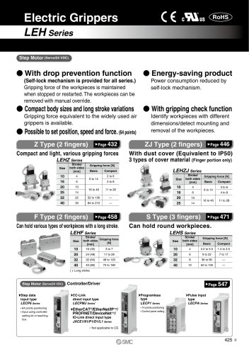 LEHZ
LEHZ67 Pages
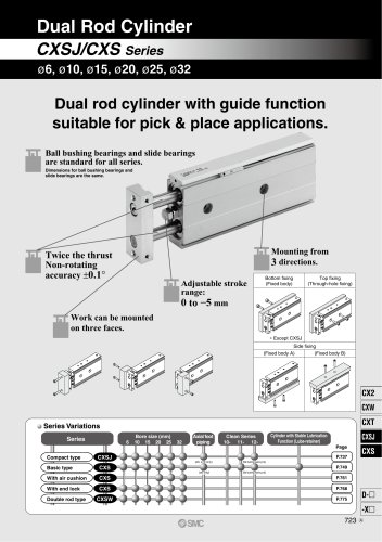 CXSJ
CXSJ60 Pages
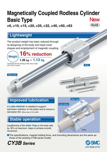 CY3B
CY3B17 Pages
 Aluminum High Vacuum Angle Valve
26 Pages
 AP Ultra High Purity
25 Pages
 IFW5 series
5 Pages
 Air Management System
64 Pages
 25A-ZSE20(F)/ISE20 Series
12 Pages
 ASG
ASG4 Pages
 IDG
IDG49 Pages
 CXSJ_M
2 Pages
 JLV20/30
8 Pages
 Series NCQ2/CQ2
252 Pages
 AC Series - Modular F.R.L. Units
70 Pages
 KQG2
KQG218 Pages
 IDF*E
IDF*E48 Pages
 AC10-A to AC40-A
82 Pages
 VQZ115, 100 Series
41 Pages
 SYJ300
60 Pages
 3000 Series
272 Pages
 MTS8
MTS823 Pages
 CXS-A
CXS-A60 Pages
 CXSL
CXSL60 Pages
 MXQR
MXQR36 Pages
 NC(D)Q2-Z
252 Pages
 LEY series
88 Pages
 MXH series
18 Pages
 KQ2
KQ2214 Pages
 Modular F.R.L. Units
108 Pages
 MXQ series
198 Pages
 Fieldbus System
92 Pages
 Fluoropolymer Piping Equipment
82 Pages
 Digital Flow Switch
24 Pages
 Vacuum Pad with Ejector
8 Pages
 Intrinsically safe Valve
43 Pages
 CQ2 series
25 Pages
 IDH, Thermo-dryer
12 Pages
 ISG
ISG10 Pages
 ISE3
ISE38 Pages
 ISE2
ISE27 Pages
 ISE1
ISE15 Pages
 ISA
ISA59 Pages
 IS3000
2 Pages
 IS10/10M/10E
4 Pages
 PSE series
44 Pages
 ISE70/75/75H
10 Pages
 ISE80
ISE8017 Pages
 ISE40A
29 Pages
 HED series
16 Pages
 HEC series
32 Pages
 HEB series
9 Pages
 HRG series
85 Pages
 HRZ series
52 Pages
 HRW series
28 Pages
 LQ series
35 Pages
 LVQ series catalog
75 Pages
 PA series
37 Pages
 EX600, Analog Input/Output Unit
59 Pages
 LER series
62 Pages
 LEJ series
58 Pages
 ISE/ZSE30A series
18 Pages
 LAT3 series
24 Pages
 LEH series
103 Pages
 CQS series
59 Pages
 CH series
175 Pages
 ARX series
12 Pages
 HRS series
47 Pages
 LES
LES59 Pages
 MHS
MHS74 Pages
 MHY
MHY27 Pages
 MHC
MHC27 Pages
 MHR
MHR30 Pages
 MHZ series
78 Pages
 MSQ
MSQ37 Pages
 MGP
MGP127 Pages
 MXS
MXS38 Pages
 NRB
NRB10 Pages
 MXW
MXW22 Pages
 MHT
MHT11 Pages
 MY3
MY354 Pages
 CQM
CQM15 Pages
 NCA1
NCA163 Pages
 CM2
CM2152 Pages
 NCM
NCM91 Pages
 NCG
NCG96 Pages
 NCRA1
NCRA15 Pages
 T/TIA
T/TIA1 Page
 KR
KR7 Pages
 KF
KF16 Pages
 KQ
KQ80 Pages
 AFF
AFF80 Pages
 AMG
AMG80 Pages
 IDF
IDF16 Pages
 HAA
HAA3 Pages
 ZFA
ZFA14 Pages
 ZA
ZA13 Pages
 MHF
MHF32 Pages
 CRB
CRB44 Pages
 D
D117 Pages
 RB
RB23 Pages
 CEP
CEP44 Pages
 rsq
rsq30 Pages
 CLK
CLK51 Pages
 MK
MK20 Pages
 CLJ
CLJ65 Pages
 MGJ
MGJ7 Pages
 ZSE30A
17 Pages
 IDFB*E
89 Pages
 ISE10
ISE1016 Pages
 ITV1000/2000
50 Pages
 AW
AW27 Pages
 NVFM200
12 Pages
 NVM100
32 Pages
 LLA*A
LLA*A36 Pages
 VX3*
VX3*41 Pages
 SY3000
158 Pages
 CH(D)2
175 Pages
 M(D)SUB
31 Pages


Archived catalogs
 Rodless cylinder
52 Pages
 ZSE1 series
12 Pages
 Rack and Pinion Rotary Actuators
37 Pages
 Special Fittings
14 Pages
 Toggle Grippers
16 Pages
 SX series
138 Pages
 ACG series
25 Pages
 C95 Pneumatic Cylinder
50 Pages
 Shock Absorber
16 Pages
 Silencer
4 Pages
 VV061 series
11 Pages
 Air Filter Catalog
18 Pages
 heavy Duty Actuators
88 Pages
 Self-seal Fittings Catalog
13 Pages
 Connectors Catalog
53 Pages

