- Products
- Catalogs
- News & Trends
- Exhibitions
CQM
1 /15Pages

CQM
1 /15Pages
Catalog excerpts

Compact Cylinder/Guide Rod Type Series CQM Lateral load resisting 2 to 4 times ∗ Compared to compact cylinder Series CQ Non-rotating accuracy ± 0.2° or less CUJ Refer to page 794 for details. Guide Rod CU CQS CQ2 RQ External dimensions Slide bearing Load can be directly mounted. CQM MU Mounting dimensions compatible with Series CQS, CQ2. Auto switch is mountable/removable even when the plate is retracted. Series Variations Series Bore size (mm) Standard stroke (mm) 5 10 15 20 25 30 35 40 45 50 75 100 Cushion D- 12, 16 CQM 20, 25 32, 40 -X Rubber bumper Individual -X 50, 63, 80, 100 Technical data 791
Open the catalog to page 1
Compact Cylinder: Guide Rod Type CQMø50, ø63, ø80, ø100 ø12, ø16, ø20, ø25, ø32, ø40, Series How to Order CQM B 20 With auto switch 10 10 M9BW CDQM B 20 Number of auto switches With auto switch Nil S n (Built-in magnet) Mounting bracket B A Through-hole (Standard) Both ends tapped (ø32 to ø100) Auto switch type Note 1) Cylinder bodies of ø12 to ø25 are common for both B (through hole) and A (both ends tapped) types. Symbol to order is unified to “B” for those sizes. Note 2) Cylinder mounting bolts are not included. Order them separately referring to Mounting Bolts for CQM on pages 796 and 797....
Open the catalog to page 2
Series CQM Plate Non-rotating Accuracy Non-rotating accuracy without load is designed to be same or less than the figures shown in the table below at the retracted cylinder end (plate). Bore size (mm) Non-rotating accuracy 12, 16 ±0.2° 20 to 100 ±0.1° +θ –θ Plate Allowable Rotational Torque Make sure to operate strictly within the allowable rotation torque range to the plate. T Operation outside of this range may result in shorter service life or damage to the devise. T Unit: N.m Cylinder stroke (mm) Bore size (mm) 5 10 15 20 25 30 35 40 45 50 75 100 12 0.11 0.10 0.08 0.07 0.07 0.06 – – – – –...
Open the catalog to page 4
Compact Cylinder: Guide Rod Type Series CQM Construction ø12 to ø25 With auto switch (Built-in magnet) ø32 to ø100 With auto switch (Built-in magnet) CUJ CU CQS CQ2 RQ CQM MU ø50 to ø100 Component Parts No. 1 Description Cylinder tube 2 Collar 3 Piston Material Note Aluminum alloy Hard anodized Aluminum alloy ø12 to ø40 Anodized Aluminum alloy casted ø50 to ø100 Chromated, Coated Aluminum alloy Chromated Stainless steel ø12 to ø25 Carbon steel ø32 to ø100 Hard chrome plated 4 Piston rod 5 Plate Aluminum alloy Anodized 6 Guide rod Stainless steel Hard chrome plated 7 Bushing Oil-impregnated sintered...
Open the catalog to page 5
Compact Cylinder: Guide Rod Type Series CQM Dimensions ø32 to ø50 2 x HA through 2 x øHB through Auto switch A V 2xP K 2 xøN through 2 x 2 x øOB counterbore with depth RB Q F øI B Z M EC EB EA øIA K (ǢKB) M EC EB EA A W B + Stroke A + Stroke L J CUJ CU 2 x 2 x RA 2 x 2 x OA CQS Both ends tapped (CQMA) CQ2 RQ (mm) Without auto switch Bore size (mm) Stroke range (mm) A B 40 23 75, 100 50 33 5 32 40 50 10 to 50 5 to 50 46.5 29.5 75, 100 56.5 39.5 10 to 50 50.5 30.5 75, 100 60.5 40.5 With auto switch P A B 50 Rc 1/8 NPT 1/8 G 1/8 Rc 1/4 NPT 1/4 G 1/4 P EA EB EC F Q 5.5 11.5 — M5 x 0.8 7.5 10.5 Rc...
Open the catalog to page 9
Compact Cylinder: Guide Rod Type Series CQM Auto Switch Mounting Bracket: Part No. Auto switch mounting surface Bore size (mm) ø12 ø16, ø20, ø25 Port side C A ø32, ø40, ø50 Port side C ø63, ø80, ø100 Port side Port side C A C A A B B B B Auto switch model Auto switch mounting surface Auto switch mounting surface Auto switch mounting surface A, B, C sides Port side Port, A, B, C sides BQ-2 BQ2-012 2 kinds of auto switch mounting brackets are used as a set. D-A9 D-A9V D-M9 D-M9V D-M9W D-M9WV D-M9AL D-M9AVL Auto switch mounting bracket not required. Auto switch mounting bracket not required. Auto...
Open the catalog to page 13
The number of surfaces and grooves where an auto switch can be mounted (as direct mounting). The number of the surfaces and grooves where the auto switch can be mounted, by switch type, are shown in the table below. Port aperture View from
Open the catalog to page 14
Series CQM Specific Product Precautions Be sure to read before handling. Refer to front matters 54 and 55 for Safety Instructions and pages 3 to 11 for Actuator and Auto Switch Precautions. Mounting Warning 1. Do not put hands or fingers between the plate and cylinder tubing. Never put hands or fingers in the gap between the plate and cylinder tubing when the piston rods are retracted. Due to the heavy power output of the cylinder, failure to comply with this directive may result in trapping and subsequent injury to the human body. Others Caution 1. This product should not be used as a stopper....
Open the catalog to page 15All SMC Corporation of America catalogs and technical brochures
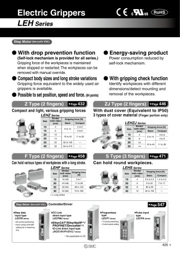 LEHZ
LEHZ67 Pages
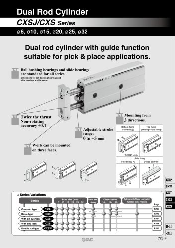 CXSJ
CXSJ60 Pages
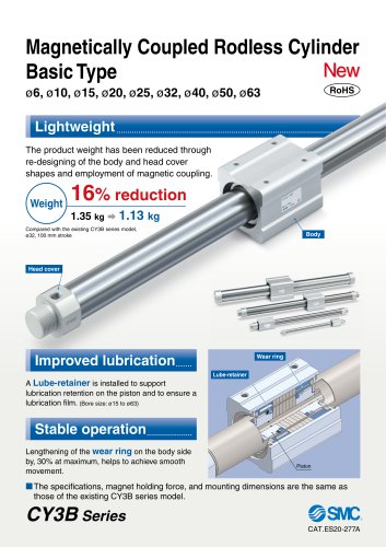 CY3B
CY3B17 Pages
 Aluminum High Vacuum Angle Valve
26 Pages
 AP Ultra High Purity
25 Pages
 IFW5 series
5 Pages
 Air Management System
64 Pages
 25A-ZSE20(F)/ISE20 Series
12 Pages
 ASG
ASG4 Pages
 IDG
IDG49 Pages
 CXSJ_M
2 Pages
 JLV20/30
8 Pages
 Series NCQ2/CQ2
252 Pages
 AC Series - Modular F.R.L. Units
70 Pages
 KQG2
KQG218 Pages
 IDF*E
IDF*E48 Pages
 AC10-A to AC40-A
82 Pages
 VQZ115, 100 Series
41 Pages
 SYJ300
60 Pages
 3000 Series
272 Pages
 MTS8
MTS823 Pages
 CXS-A
CXS-A60 Pages
 CXSL
CXSL60 Pages
 MXQR
MXQR36 Pages
 NC(D)Q2-Z
252 Pages
 LEY series
88 Pages
 MXH series
18 Pages
 KQ2
KQ2214 Pages
 Modular F.R.L. Units
108 Pages
 MXQ series
198 Pages
 Fieldbus System
92 Pages
 Fluoropolymer Piping Equipment
82 Pages
 Digital Flow Switch
24 Pages
 Vacuum Pad with Ejector
8 Pages
 Intrinsically safe Valve
43 Pages
 CQ2 series
25 Pages
 IDH, Thermo-dryer
12 Pages
 ISG
ISG10 Pages
 ISE3
ISE38 Pages
 ISE2
ISE27 Pages
 ISE1
ISE15 Pages
 ISA
ISA59 Pages
 IS3000
2 Pages
 IS10/10M/10E
4 Pages
 PSE series
44 Pages
 ISE70/75/75H
10 Pages
 ISE80
ISE8017 Pages
 ISE40A
29 Pages
 HED series
16 Pages
 HEC series
32 Pages
 HEB series
9 Pages
 HRG series
85 Pages
 HRZ series
52 Pages
 HRW series
28 Pages
 LQ series
35 Pages
 LVQ series catalog
75 Pages
 PA series
37 Pages
 EX600, Analog Input/Output Unit
59 Pages
 LER series
62 Pages
 LEJ series
58 Pages
 ISE/ZSE30A series
18 Pages
 LAT3 series
24 Pages
 LEH series
103 Pages
 CQS series
59 Pages
 CH series
175 Pages
 ARX series
12 Pages
 HRS series
47 Pages
 LES
LES59 Pages
 MHS
MHS74 Pages
 MHY
MHY27 Pages
 MHC
MHC27 Pages
 MHR
MHR30 Pages
 MHZ series
78 Pages
 MSQ
MSQ37 Pages
 MGP
MGP127 Pages
 MXS
MXS38 Pages
 NRB
NRB10 Pages
 MXW
MXW22 Pages
 MHT
MHT11 Pages
 MY3
MY354 Pages
 NCA1
NCA163 Pages
 CM2
CM2152 Pages
 NCM
NCM91 Pages
 NCG
NCG96 Pages
 NCRA1
NCRA15 Pages
 CS2
CS232 Pages
 T/TIA
T/TIA1 Page
 KR
KR7 Pages
 KF
KF16 Pages
 KQ
KQ80 Pages
 AFF
AFF80 Pages
 AMG
AMG80 Pages
 IDF
IDF16 Pages
 HAA
HAA3 Pages
 ZFA
ZFA14 Pages
 ZA
ZA13 Pages
 MHF
MHF32 Pages
 CRB
CRB44 Pages
 D
D117 Pages
 RB
RB23 Pages
 CEP
CEP44 Pages
 rsq
rsq30 Pages
 CLK
CLK51 Pages
 MK
MK20 Pages
 CLJ
CLJ65 Pages
 MGJ
MGJ7 Pages
 ZSE30A
17 Pages
 IDFB*E
89 Pages
 ISE10
ISE1016 Pages
 ITV1000/2000
50 Pages
 AW
AW27 Pages
 NVFM200
12 Pages
 NVM100
32 Pages
 LLA*A
LLA*A36 Pages
 VX3*
VX3*41 Pages
 SY3000
158 Pages
 CH(D)2
175 Pages
 M(D)SUB
31 Pages


Archived catalogs
 Rodless cylinder
52 Pages
 ZSE1 series
12 Pages
 Rack and Pinion Rotary Actuators
37 Pages
 Special Fittings
14 Pages
 Toggle Grippers
16 Pages
 SX series
138 Pages
 ACG series
25 Pages
 C95 Pneumatic Cylinder
50 Pages
 Shock Absorber
16 Pages
 Silencer
4 Pages
 VV061 series
11 Pages
 Air Filter Catalog
18 Pages
 heavy Duty Actuators
88 Pages
 Self-seal Fittings Catalog
13 Pages
 Connectors Catalog
53 Pages

