- Products
- Catalogs
- News & Trends
- Exhibitions
CEP
1 /44Pages

CEP
1 /44Pages
Catalog excerpts

Stroke Reading Cylinder and Counter > Output: 5 points (Bank switching: 20 points) 31 points (Binary output) High Precision Stroke Reading Cylinder Stroke Reading
Open the catalog to page 1
Measurement is possible throughout the full stroke range. Hp home position can be anywhere within the cylinder stroke. When the counter is reset by pressing the cylinder rod to the reference plane, that point becomes the home position. Can be used in an environment where the product is exposed to fluids (water, oil, coolant, etc.) Series CEP1 With special scraper as standard * The standard type of Series CE1 does not come with a scraper. Series CE1 Special order (with scraper) * Contact SMC since cylinders with a scraper are special orders. High Precision Stroke Reading Cylinder (CEP1) • Special...
Open the catalog to page 2
Application Examples Parts inspection parts, discriminates between good and defective articles, hydraulic cylinder by detecting its Even if the size of the workpiece changes, the point of press-in completion can be easily changed. deceleration point Since the deceleration point of the die easily changed after replacement of Length/breadth discrimination Distinguishes either lengthwise or crosswise while correcting the Maintains a constant height of I measuring workpiece height. ! Detection of lifter position lifter's stroke. I Inspection of machined holes Can detect machined hole depth, burrs...
Open the catalog to page 3
Stroke Reading Cylinder Series Measurement Principle The amount of rod movement in the stroke reading cylinder is detected using an MR element (magnetic resistance element) whose resistance value changes due to magnetic force. The detection unit containing this MR element is called the sensor head. An amplifying circuit and a dividing circuit are required to produce output which can be read by the counter, and these are attached to the cylinder case. The sensor head and amplifier section together are referred to as the sensor unit. Sensor head Cylinder unit The stroke reading cylinder is equipped...
Open the catalog to page 4
Specific Product Precautions Be sure to read before handling. Refer to front matters 42 and 43 for Safety Instructions and pages 3 to 11 for Actuator and Auto Switch Precautions. 1. When screwing a nut or fitting, etc. onto the threaded section at the end of the piston rod, return the piston rod to its fully retracted position, and grasp the exposed portion of the rod across two parallel sides with a wrench. In the case of the high precision stroke reading cylinder, there are no parallel sides. Secure the workpiece with a double nut. Note) Do not apply rotational torque to the piston rod. 2....
Open the catalog to page 5
High Precision Stroke Reading Cylinder Non-rotating Piston Type Note) CE compliant: When connecting power supply voltage 24 VDC) operation manual for details. High precision stroke reading cylinder Mounting style Bore size Standard cylinder stroke (mm) Refer to "Standard Stroke" on page 1445. Referto page 1445 for details. Number of auto switches Auto switch Nil I Without auto switch (Built-in magnet) For the applicable auto switch model, refer to Sensor cable length Applicable counter Mounting Bracket Part No. Cable length Applicable AutO Switch/Refer to pages 1719 to I827 for further information...
Open the catalog to page 7
High Precision Stroke Reading Cylinder Non-rotating Piston Type SOflOS Cylinder Specifications Made to Order Specifications (For details, refer to page 1918.) Fluororubber seals Sensor Specifications Note 1) This includes the digital display error of the counter (CEU5). When strokes are over 100 mm, accuracy is ±0.05 mm. Moreover, the overall accuracy after mounting on equipment will vary depending on mounting conditions and the environment. Therefore, the customer should calibrate the Note 2) Except for the connector, the cylinder section is the equivalent of an SMC water resistant Cylinder...
Open the catalog to page 8
Mass (Without mounting bracket/connector)_ Auto Switch Proper Mounting Position Regarding dimensions for the auto switch proper mounting position (at stroke end), refer to page 1452. Electrical Wiring Output type The output signal of the high precision stroke reading cylinder is A/B phase difference output (open collector output) as shown in the figure below. The relation between the movement distance and the signal output of the high precision stroke reading cylinder is that for each 0.04 mm of movement a one pulse signal is output to both output terminals A and B. In order to measure with a...
Open the catalog to page 9
High Precision Stroke Reading Cylinder Non-rotating Piston Type Series Component Parts Component Parts * Since there is a possibility of improper operation, please contact SMC regarding the replacement of seals.
Open the catalog to page 10
Direct mounting, rod side tapped style: Metal connector Width across flats 8 4 X M5 X 0.8 depth 6 (Bottom 04.3 through-hole)
Open the catalog to page 11
High Precision Stroke Reading Cylinder Non-rotating Piston Type Series Foot style: Rod side flange style:
Open the catalog to page 12
Auto Switch Proper Mounting Position (Detection at Stroke End) Operating Range Auto switch Note) Adjust the auto switch after confirming the operating conditions in the actual setting. ► Since the operating range is provided as a guideline including hysteresis, it cannot be guaranteed (assuming approximately ±30% dispersion). It may vary substantially depending on an ambient Other than the models listed in "How to Order", the following auto switches are applicable. * For solid state auto switches, auto switches with a pre-wired connector are also available. Referto pages 1784 and 1785 * Normally...
Open the catalog to page 15
Stroke Reading Cylinder Note) CE compliant: When connecting Refer to the counter operation Mounting style* Bore size Cable length •Auto switch auto switches Without auto switch (Built-in magnet) switch model, refer to Standard cylinder stroke (mm) Refer to "Standard Stroke" on page 1455 (Applicable bore size 040 to 063) Applicable counter Cable length * 012, 020, 032: Without cushion only. Applicable AutO Switch/Refer to pages 1719 to I827 for further information on auto switches. ** Water resistant type auto switches can be mounted on the above models, but in such case SMC cannot guarantee water...
Open the catalog to page 17All SMC Corporation of America catalogs and technical brochures
 LEHZ
LEHZ67 Pages
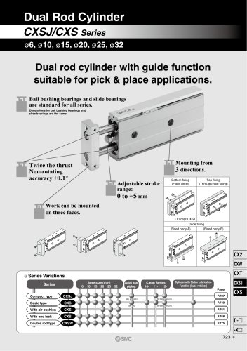 CXSJ
CXSJ60 Pages
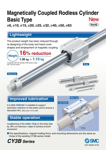 CY3B
CY3B17 Pages
 Aluminum High Vacuum Angle Valve
26 Pages
 AP Ultra High Purity
25 Pages
 IFW5 series
5 Pages
 Air Management System
64 Pages
 25A-ZSE20(F)/ISE20 Series
12 Pages
 ASG
ASG4 Pages
 IDG
IDG49 Pages
 CXSJ_M
2 Pages
 JLV20/30
8 Pages
 Series NCQ2/CQ2
252 Pages
 AC Series - Modular F.R.L. Units
70 Pages
 KQG2
KQG218 Pages
 IDF*E
IDF*E48 Pages
 AC10-A to AC40-A
82 Pages
 VQZ115, 100 Series
41 Pages
 SYJ300
60 Pages
 3000 Series
272 Pages
 MTS8
MTS823 Pages
 CXS-A
CXS-A60 Pages
 CXSL
CXSL60 Pages
 MXQR
MXQR36 Pages
 NC(D)Q2-Z
252 Pages
 LEY series
88 Pages
 MXH series
18 Pages
 KQ2
KQ2214 Pages
 Modular F.R.L. Units
108 Pages
 MXQ series
198 Pages
 Fieldbus System
92 Pages
 Fluoropolymer Piping Equipment
82 Pages
 Digital Flow Switch
24 Pages
 Vacuum Pad with Ejector
8 Pages
 Intrinsically safe Valve
43 Pages
 CQ2 series
25 Pages
 IDH, Thermo-dryer
12 Pages
 ISG
ISG10 Pages
 ISE3
ISE38 Pages
 ISE2
ISE27 Pages
 ISE1
ISE15 Pages
 ISA
ISA59 Pages
 IS3000
2 Pages
 IS10/10M/10E
4 Pages
 PSE series
44 Pages
 ISE70/75/75H
10 Pages
 ISE80
ISE8017 Pages
 ISE40A
29 Pages
 HED series
16 Pages
 HEC series
32 Pages
 HEB series
9 Pages
 HRG series
85 Pages
 HRZ series
52 Pages
 HRW series
28 Pages
 LQ series
35 Pages
 LVQ series catalog
75 Pages
 PA series
37 Pages
 EX600, Analog Input/Output Unit
59 Pages
 LER series
62 Pages
 LEJ series
58 Pages
 ISE/ZSE30A series
18 Pages
 LAT3 series
24 Pages
 LEH series
103 Pages
 CQS series
59 Pages
 CH series
175 Pages
 ARX series
12 Pages
 HRS series
47 Pages
 LES
LES59 Pages
 MHS
MHS74 Pages
 MHY
MHY27 Pages
 MHC
MHC27 Pages
 MHR
MHR30 Pages
 MHZ series
78 Pages
 MSQ
MSQ37 Pages
 MGP
MGP127 Pages
 MXS
MXS38 Pages
 NRB
NRB10 Pages
 MXW
MXW22 Pages
 MHT
MHT11 Pages
 MY3
MY354 Pages
 CQM
CQM15 Pages
 NCA1
NCA163 Pages
 CM2
CM2152 Pages
 NCM
NCM91 Pages
 NCG
NCG96 Pages
 NCRA1
NCRA15 Pages
 CS2
CS232 Pages
 T/TIA
T/TIA1 Page
 KR
KR7 Pages
 KF
KF16 Pages
 KQ
KQ80 Pages
 AFF
AFF80 Pages
 AMG
AMG80 Pages
 IDF
IDF16 Pages
 HAA
HAA3 Pages
 ZFA
ZFA14 Pages
 ZA
ZA13 Pages
 MHF
MHF32 Pages
 CRB
CRB44 Pages
 D
D117 Pages
 RB
RB23 Pages
 rsq
rsq30 Pages
 CLK
CLK51 Pages
 MK
MK20 Pages
 CLJ
CLJ65 Pages
 MGJ
MGJ7 Pages
 ZSE30A
17 Pages
 IDFB*E
89 Pages
 ISE10
ISE1016 Pages
 ITV1000/2000
50 Pages
 AW
AW27 Pages
 NVFM200
12 Pages
 NVM100
32 Pages
 LLA*A
LLA*A36 Pages
 VX3*
VX3*41 Pages
 SY3000
158 Pages
 CH(D)2
175 Pages
 M(D)SUB
31 Pages


Archived catalogs
 Rodless cylinder
52 Pages
 ZSE1 series
12 Pages
 Rack and Pinion Rotary Actuators
37 Pages
 Special Fittings
14 Pages
 Toggle Grippers
16 Pages
 SX series
138 Pages
 ACG series
25 Pages
 C95 Pneumatic Cylinder
50 Pages
 Shock Absorber
16 Pages
 Silencer
4 Pages
 VV061 series
11 Pages
 Air Filter Catalog
18 Pages
 heavy Duty Actuators
88 Pages
 Self-seal Fittings Catalog
13 Pages
 Connectors Catalog
53 Pages

