- Catalogs
- SMAY sp. z o.o.
- Type PWW multi-blade dampers
Type PWW multi-blade dampers
1 /6Pages
Type PWW multi-blade dampers
1 /6Pages
Catalog excerpts
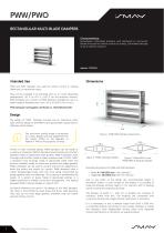
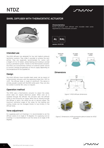
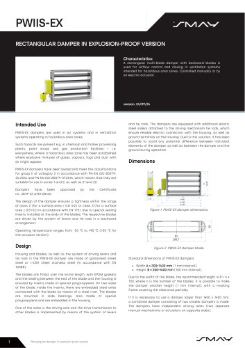
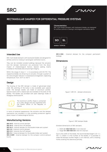
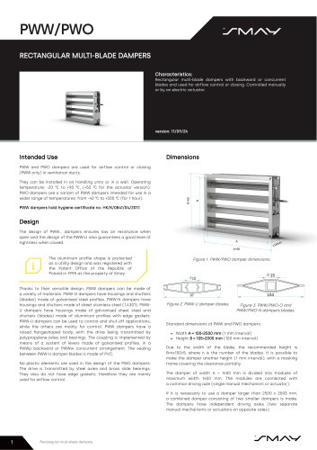
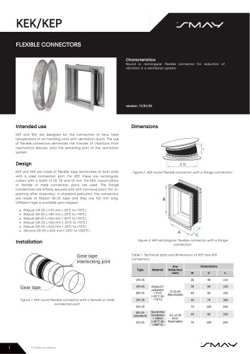
PWW/PWO RECTANGULAR MULTI-BLADE DAMPERS Characteristics: Rectangular multi-blade dampers with backward or concurrent blades and used for airflow control or closing. Controlled manually or by an electric actuator. They can be installed in air handling units or in a wall. Operating temperature: -20 °C to +90 °C, (+50 °C for the actuator version). PWO dampers are a variant of PWW dampers intended for use in a wider range of temperatures: from -40 °C to +300 °C (for 1 hour). PWW and PWO dampers are used for airflow control or closing (PWW only) in ventilation ducts. PWW dampers hold hygiene certificate no. HK/K/0841/04/2017. Design The design of PWW… dampers ensures low air resistance when open and the design of the PWW-U also guarantees a good level of tightness when closed. The aluminium profile shape is protected as a utility design and was registered with the Patent Office of the Republic of Poland in 1995 as the property of Smay. Figure 1. PWW/PWO damper dimensions. Thanks to their versatile design, PWW dampers can be made of a variety of materials. PWW-O dampers have housings and shutters (blades) made of galvanised steel profiles. PWW-N dampers have housings and shutters made of sheet stainless steel (1.4301). PWWU dampers have housings made of galvanised sheet steel and shutters (blades) made of aluminium profiles with edge gaskets. PWW-U dampers can be used to control and shut-off applications, while the others are mainly for control. PWW dampers have a raised flangeshaped body, with the drive being transmitted by polypropylene axles and bearings. The coupling is implemented by means of a system of levers made of galvanised profiles, in a PWWp backward or PWWw concurrent arrangement. The sealing between PWW-U damper blades is made of PVC. No plastic elements are used in the design of the PWO dampers. The drive is transmitted by steel axles and brass slide bearings. They also do not have edge gaskets; therefore they are mainly used for airflow control. Figure 2. PWW-U damper blades. Figure 3. PWW/PWO-O and PWW/PWO-N dampers blades. Standard dimensions of PWW and PWO dampers: Width A = 100÷2500 mm (1 mm interval) Height B = 105÷2005 mm (100 mm interval) Due to the width of the blade, the recommended height is B=nx100+5, where n is the number of the blades. It is possible to make the damper another height (1 mm interval), with a masking frame covering the clearance partially. The damper of width A > 1400 mm is divided into modules of maximum width 1400 mm. The modules are connected with a common driving axle (single manual mechanism or actuator). If it is necessary to use a damper larger than 2500 x 2005 mm, a combined damper consisting of two smaller dampers is made. The dampers have independent driving axles (two separate manual mechanisms or actuators on opposite sides). Rectangular multi-blade
Open the catalog to page 1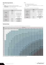
Manufacturing Versions Drive: T1 – Damper with an actuator T2 – Damper with a manual mechanism T3 – Damper with an extended axle (for the actuator installation) Type: PWW-U – Shut-off damper (a baffle with a gasket). PWW-O/PWO-O – Control damper (a baffle without a gasket), PWW-N/PWO-N – Stainless steel damper Table 2. Types and characteristics of PWO dampers. Table 1. Types and characteristics of PWW dampers. PWW-x Housing: PWW-O: Housing: Galvanised sheet steel Galvanised sheet steel Stainless steel sheet Flange-shaped body Sheet stainless steel Lever gear Mechanism: Flange-shaped body Brass...
Open the catalog to page 2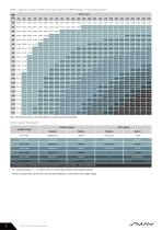
Table 4. Types of actuators and the net surface area for the PWO damper in a fully open position. Height B, [mm] Note: the parameters given in the table apply to the version with backward blades Table 5. Type of the actuator. without a spring Actuator torque Combined damper consisting of several smaller dampers. For a custom design – please contact Smay. (*) - Combined damper 2 x … Nm requires the use of two smaller dampers with separate actuators. The given actuator types can be used in several variants differing in communication and supply voltage. Rectangular multi-blade damper
Open the catalog to page 3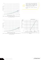
Pressure loss for a custom-height damper (with a masking frame covering the clearance partially) is comparable to the pressure loss for the nearest smaller standard height read from Chart 1. Δp (600 x 460) ≈ Δp (600 x 405) from Chart 1 Chart 1. Pressure loss for standard-height PWW and PWO dampers (in a fully open position). Chart 2. Pressure loss for standard-height PWW and PWO dampers (in a fully open position). Rectangular multi-blade dampers Chart 3. Air leaks through the PWW-U damper baffle (in a fully closed positio
Open the catalog to page 4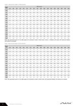
Table 6. Approximate weight of PWW dampers. Rectangular multi-blade dampers
Open the catalog to page 5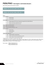
Rectangular multi-blade dampers
Open the catalog to page 6All SMAY sp. z o.o. catalogs and technical brochures
 SDR - Round diffuser
2 Pages
 PJB single-blade air dampers
3 Pages
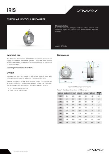 IRIS
IRIS2 Pages
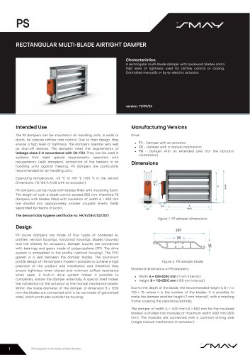 PS multi-blade dampers
5 Pages
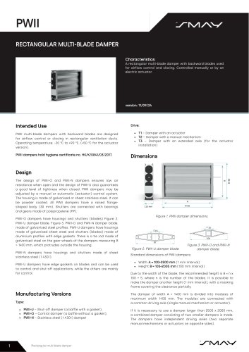 PWII Multi-blade dampers
5 Pages
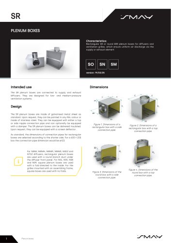 SR Plenum boxes
4 Pages
 KEP/KEK Flexible connectors
2 Pages
 Brochure SMAY UK 2025
36 Pages
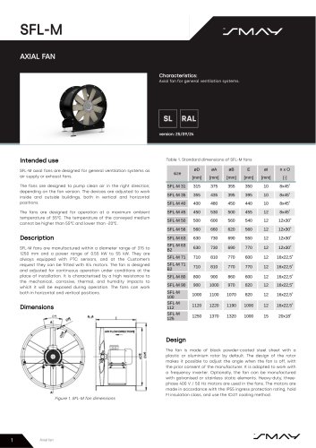 SFL-M
SFL-M3 Pages
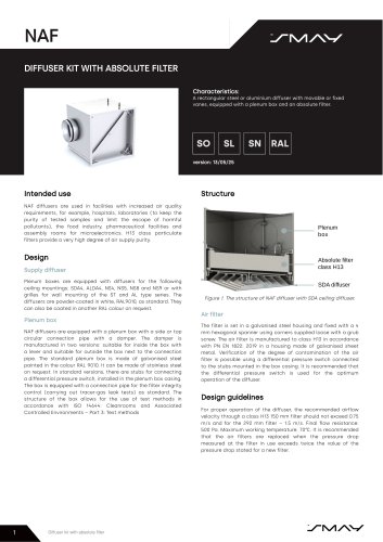 NAF
NAF6 Pages
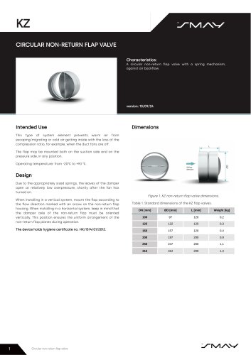 KZ
KZ3 Pages
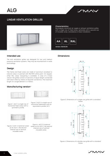 ALG
ALG5 Pages
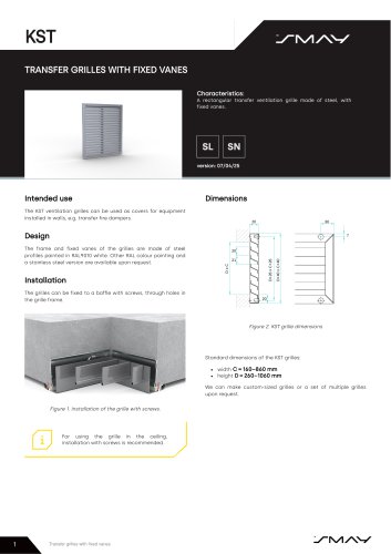 KST
KST3 Pages