SMK900
1 /55Pages

SMK900
1 /55Pages
Catalog excerpts

SMK900 Portia Radio Module Datasheet
Open the catalog to page 1
2.2 Mesh Network Systems . . . . . . . . . . . . . . . . . . . . . . . . . . . . . . . . . . . 2.3 Frequency Hopping Implications . . . . . . . . . . . . . . . . . . . . . . . . . . . . . . Dynamic parameters . . . . . . . . . . . . . . . . . . . . . . . . . . . . . . . . . Broadcast Frame Structure . . . . . . . . . . . . . . . . . . . . . . . . . . . . . 10 3.2 SMK900 Addressing and Network Segregation . . . . . . . . . . . . . . . . . . . . . . 11 3.3 Transparent and Protocol‐Formatted Mode . . . . . . . . . . . . . . . . . . . . . . . . 11 3.3.1 4.1 Description . . . . . . . . . . . . . ....
Open the catalog to page 2
10.1 Portia Adapter Board . . . . . . . . . . . . . . . . . . . . . . . . . . . . . . . . . . . . . 51 10.2 Arduino‐Compatible Shield . . . . . . . . . . . . . . . . . . . . . . . . . . . . . . . . . . 51 11 Certification Information
Open the catalog to page 4
Typical structure of periodic network broadcast cycles for the DY N = 1, 2, 4, 1, 1, 5 configuration . . . . . . . . . . . . . . . . . . . . . . . . . . . . . . . . . . . . . . . . . 11 Mesh Network Triggers . . . . . . . . . . . . . . . . . . . . . . . . . . . . . . . . . . . . 12 Module Through Hole Pinout . . . . . . . . . . . . . . . . . . . . . . . . . . . . . . . . 15 Through Holes Mounting . . . . . . . . . . . . . . . . . . . . . . . . . . . . . . . . . . . 18
Open the catalog to page 5
Virtual Machine Triggers . . . . . . . . . . . . . . . . . . . . . . . . . . . . . . . . . . . 13 Calculating the effective baud rate fBAU D . . . . . . . . . . . . . . . . . . . . . . . . . 14 Standard baud rates list . . . . . . . . . . . . . . . . . . . . . . . . . . . . . . . . . . . . 15 Module Pinout (continued) . . . . . . . . . . . . . . . . . . . . . . . . . . . . . . . . . . 17 Protocol‐Formatted Common Header . . . . . . . . . . . . . . . . . . . . . . . . . . . 26 Packet Type Decoding . . . . . . . . . . . . . . . . . . . . . . . . . . . . . . . . . . . . 27 Packet Type Decoding ....
Open the catalog to page 6
TXAirCmdWrapper (command wrapping another command for remoting) . . . . . . . 42 RXAirCmdWrapper (event wrapping remote reply) . . . . . . . . . . . . . . . . . . . . 43 Register Table (continued) . . . . . . . . . . . . . . . . . . . . . . . . . . . . . . . . . . 45 MeshExecActiveFlag Bit‐Mask Register . . . . . . . . . . . . . . . . . . . . . . . . . . . 49 Relevant Sniff Flags . . . . . . . . . . . . . . . . . . . . . . . . . . . . . . . . . . . . . . 49 Flags Enabling Special Notification UART Messages . . . . . . . . . . . . . . . . . . . 50
Open the catalog to page 7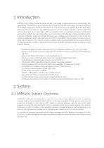
1 Introduction SMK900 transceivers provide for highly‐reliable, long‐range, and low power mesh networking radio applications. They use frequency hopping spread spectrum (FHSS) technology to ensure resistance to multipath fading and robustness, as well as for compliance with 900 MHz unlicensed band regu‐ lations in Canada and the US. The SMK900 supports a CTS‐enabled serial port interface with data rates ranging from 1.2 to 230.4 kbps, with two possible modes of operation (transparent ASCII and protocol‐formatted). For easy integration, error correction and buffering is all accomplished within...
Open the catalog to page 8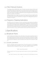
2.2 Mesh Network Systems The topology used by a SMK900 radio is that of a broadcast‐only mesh network, with sleep‐wake synchronization handled by the gateway. This mean that any SMK900 radio transmission sends a broadcast to the whole mesh network. There are no provisions for pure unicast messaging, and such needs are usually handled by integrator using a higher‐level protocol sitting on top of the SMK900 protocol. The maximum of broadcast transmission of the same messages over the mesh network depend on the number of hops allowed. Multiple independent mesh networks may coexist in the same physical...
Open the catalog to page 9
Not line of sight ** Line of sight BI: number of node to gateway messages (also called broadcast in phase count), Nh: the maximum number of hops for the network (i.e. maximum number of time a message can be relayed from node to node), Nr: number of random-access specialized hop slots (called redux),
Open the catalog to page 10
R: specialized slotting mechanism enabled D: inverted sleep‐wake duty cycle ratio D (min. value is 1), The broadcast time can be then calculated as: TBCAST [msec] = 10(NH (BO + BI ) + NR · R) The interval between each broadcast is: TIN T ERV AL [msec] = TBCAST · D For the vast majority of applications, the default settings, where BO = BI = 1 and R = 0, are applicable, in which case the timing equations simplify to: TBCAST [msec] = 20 · NH TIN T ERV AL [msec] = TBCAST · D Allowable values for each of those are, with default values in (boldface): BO : [(1), 2, 3, 4] BI : [(1), 2, 3, 4] NH : [1,...
Open the catalog to page 11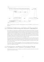
Regular broadcast \ phase level Regular broadcast cycle Phase redux Regular broadcast cycle Broadcast fCondTEoriaTWl Periodic sleep-wake cycle Figure 1: Typical structure of periodic network broadcast cycles for the DYN = 1, 2,4,1,1, 5 configuration Each module has a unique factory-configured 3-byte address, called the MAC address. In the standard protocol-based serial data mode, this MAC address can be used to specify to which destination a message is intended, although this is not a necessary part of the protocol due to the fact that every message is treated as a broadcast to all nodes. The...
Open the catalog to page 12
The transparent mode allows for basic, unsynchronized integration which emulate a simple point-to-multipoint serial link between a gateway and its nodes. In this case, the message is assumed to be of standard ASCII format, with the special ASCII terminator characters 0x13 (Carry) or 0x10 (Line Feed) are used as markers to trigger the end of a message stream, and thus to trigger transmission over radio waves. Protocol-formatted messages also referred to as Application Programing Interface (API) are discussed in the following sections. protocol-formatted messages usea start-of-message marker, followed...
Open the catalog to page 13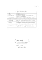
Table 2: Virtual Machine Triggers
Open the catalog to page 14
The SMK900 module provides multiple application interfaces: a primary communication serial port (CTS enabled), a dedicated I2C port (Master mode only), and 13 generic digital I/O. The latter can be reconfigured to ADC (2x), to DAC (2x) or to PWM hardware signalling or clock generation (2x). The SMK900 transceiver can also use advanced peripherals such as hardware timers and event capture/compare within custom bytecode executed by its VM engine. The host processor is tied to the SMK900 module over a full-duplex UART interface serial port with CTS pin hardware control. Baud rate is configurable...
Open the catalog to page 15All Smartrek Technologies Inc. catalogs and technical brochures
 Smartrek monitoring
142 Pages
 Quick Start Guide
11 Pages
 Smartrek Raven-Eye 2
2 Pages
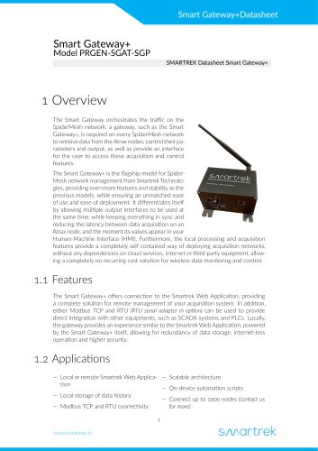 Smart Gateway+
10 Pages
- Flowmeter
- Temperature probe
- Liquid flow monitor
- Resistance temperature sensor
- Waterproof flow meter
- Level probe
- Stainless steel flow monitor
- Liquid level sensor
- Pressure probe
- Wireless remote control
- Industrial remote control
- Remote control with buttons
- Analog level sensor
- Industrial gateway
- Fieldbus gateway
- RS485 flow monitor
- Modbus flow monitor
- Membrane pressure sensor
- RTD temperature sensor