
- Catalogs
- Smart Motor Devices
- PROGRAMMABLE STEP MOTOR CONTROLLER SMSD-1.5


- Company
- Products
- Catalogs
- News & Trends
- Exhibitions
PROGRAMMABLE STEP MOTOR CONTROLLER SMSD-1.5

PROGRAMMABLE STEP MOTOR CONTROLLER SMSD-1.5
- Movement Commands:
- Vddd: Move motor by 'ddd' steps (1 to 10,000,000).
- MH, ML, HM: Indefinite movement until a signal is received.
- SPddd: Pause for 'ddd' milliseconds.
- LL and JPddd: Set label for cycle operation and repeat.
- WL and WH: Indefinite pause until a signal is received.
- E10: Command successfully accepted.
- E13: Error in executing program.
- E14: Program execution completed.
- E15: Communication error.
- E16: Command error.
- E19: Command data error.
- Standby Mode: Green LED.
- Program Executing Mode: Red LED.
- Waiting for External Signal: Red LED.
- Commands Loading: Orange LED.
- Reading Commands: Orange LED.
- Temporary Stop: Orange LED.
- Executing Program Error: Blinking Orange LED.
Catalog excerpts
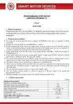
PROGRAMMABLE STEP MOTOR CONTROLLER SMSD-1.5 Manual SMSD.15.002 1. Product designation Programmable step motor controller SMSD-1.5 is designed to operate with stepper motor with maximum current per phase up to 1.6 Amp. There are three control modes provided: programmable, manual or simple driver. · · · · · · · · · · · 2. Functions and possibilities Recording the operation algorithm from a computer to EEPROM of the unit as a sequence of ASCII commands. Reading the saved algorithm from the EEPROM to a computer. In the programmable mode: control the stepper motor as per the program, saved in the unit’s memory. Speed, acceleration/deceleration, displacement, direction of the stepper motor are set as a sequence of execution commands and is storage in the nonvolatile memory of the unit. In the simple driver mode: the unit receives logic signals “PULS” and “DIR” – 0VDC low level and 824VDC high level. In the manual mode: the unit receives analog signal “Speed” (voltage signal 0-5VDC, internal or external potentiometer) and digital signals “Reverse” and “Enable”. For synchronized operation of several SMSD-1.5 units and other devices there are 3 digital inputs and one output relay are provided. These inputs and output relay are used in the programmable mode. The unit can operate and be controlled by a computer or in a standalone mode. There is zero positioning function provided: start zero search by a command or by a signal on the digital input. Stop zero searching movement as input signal is received. The function provides homing by an individual input. The unit stops motor motion as receives a signal on an “Enable” input. The unit changes rotation direction as receives a signal on a “Reverse” input (in the manual and programmable modes). The microstepping can be changed on-fly in the manual and programmable modes. 3. Common characteristic: Number of controlled stepper motors Maximum output current per phase, Amp Minimum output current per phase, Amp Microstepping modes Pulses frequency in programmable and manual modes, Hz Voltage input, VDC Dimensions, mm no more Inputs DIR, STEP (simple driver mode): High voltage level, VDC
Open the catalog to page 1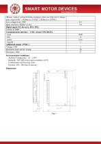
(Please, connect current-limiting resistance when use high level voltage more, than 8VDC: 1 KOhm for 12VDC, 2 KOhm for 24VDC). Low voltage level, VDC Input resistance, KOhm no less Digital inputs EN, Reverse, BX1, BX2: Contact to GND Communication interface - USB, virtual COM RS232: - baud - bits - parity - stop bit Additional output «5VDC»: Voltage, VDC Maximum load current, mAmp Resistance, Ohm Environmental Conditions: Ambient Temperature: -25…+50°C Humidity: 90% RH or less upon condition +25°C Condensation and freezing: none Pressure: 650…800 mm of mercury Dimensions:
Open the catalog to page 2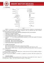
img 2 SMSD-1.5 is designed as a circuit plate with electronics elements, installed on a heatsink plate and covered with a metal case. Besides electronic components, there are indicating and control elements, connection terminals and connectors on the board: · terminal screws for power supply, stepmotor windings and control circuit connection; · USB plug for a computer connection; · control buttons “Reset”, “Homing”, “Start”; · internal preset potentiometer «V» to adjust speed in the manual mode.; · connector " " for an external potentiometer connection to control motor speed in the manual mode;...
Open the catalog to page 3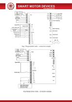
SMART MOTOR DEVICES Reverse input Enable input Reset input Home input Current adjusting Speed adjusting Start button Reset button Home button Enable Input Logic signal source
Open the catalog to page 4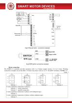
Img 5 Manual mode – connection example GND +VCC Img 6 NPN switch connection example Motor connection The SMSD-1.5 controller provides operation with 2 or 4-phase stepper motors, 4, 6 or 8 wires. Winding connection examples are in the table 2. Connect step motor wires to A, A*, B and B* terminals of SMSD-1.5. Table. 2 Scheme 1 Scheme 2 Scheme 3 8 wires stepmotor connection (4 phases): Scheme 1 – serial connection; Scheme 2 – parallel connection. 6 wires stepmotor connection (2 phases with midpoint taps): Scheme 3; 4 wires stepmotor connection (2 phases without midpoint taps): Scheme 4 .
Open the catalog to page 5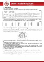
6. Before starting 1. Make sure the power supply is turned off. 2. Chose the suitable operation mode and set microswitches SW1 and SW2 according to the table 3. Table .3 Operation mode Simple driver Control As per the preset motion algorithm, saved in the controller’s memory. Algorithm consists of a sequence of commands – simple instructions. Pulse and Dir logic signals – low and high level voltage. Speed is adjusted by a potentiometer or analog signal 0-5VDC, direction is changed by a logic signal (pulse). 3. Chose suitable microstepping mode and set microswitches SW3 – SW5 according to the...
Open the catalog to page 6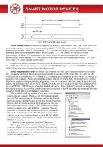
Img 8 STEP and DIR input signals - In the manual mode (connection example on the image 5) close contacts “start” and “GND” to run the motor, adjust speed by the potentiometer or analog signal 0-5VDC. The motor speed is changed by the " is closed. To connect external potentiometer set the internal potentiometer “SPEED” when jumper " " and connect on this place external minimum speed by internal potentiometer, remove jumper " potentiometer 10 KOhm. To adjust speed by the analog signal set the minimum speed by internal " and connect on this place contacts of analog signal source (“0V“ at the potentiometer,...
Open the catalog to page 7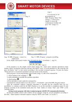
It is necessary to set port properties in SMC_Program. Menu “Port settings” > «Chose port» (image 12) chose the connected port number and press “Ok” (image 13). Img. 11. SMC_Program – program assembling Img. 10. SMC_Program – control via simple panel In the simple control panel window (img 10) check the box 1, (coordinate 1 – img.14). img 14 If the program is in the simple control mode (image 10) - input motor operation parameters (steps number, speed, acceleration, direction) and press the button “write” to record parameters to the controller and press the button “start” to start motion according...
Open the catalog to page 8All Smart Motor Devices catalogs and technical brochures
 Smart Motor Devices 2021 catalog
14 Pages
Archived catalogs
 Smart Motor Devices 2021
21 Pages
 DC brush motors
4 Pages


