
- Catalogs
- Smart Motor Devices
- DC BRUSH MOTORCONTROLLER BMSD


- Company
- Products
- Catalogs
- News & Trends
- Exhibitions
DC BRUSH MOTORCONTROLLER BMSD

DC BRUSH MOTORCONTROLLER BMSD
The BMSD brush motor controller is designed to manage DC brush motors, with or without an encoder, handling motor speed, direction, and smooth start/stop functions for motors up to 12A. Parameters can be configured via RS-485 interface or controller inputs.
- Power Supply Voltage: 10-28 VDC
- Max Motor Current: 12A
- Current Protection: 16A
- Max Motor Voltage: 0.98*Vsup
- Acceleration/Deceleration: Min Vsup/8, Max 3Vsup
- External Speed Adjustment: 0-5V or 1-10 kOhm potentiometer
- Encoder Power Supply: 5VDC, 50mA max
- Max Motor Speed: 15000 RPM
- Environmental Conditions: -25 to +50°C, 90% RH max
The controller consists of a circuit board within a metal case, featuring terminal screws for connections, a "START/STOP" button, internal potentiometers for speed, acceleration, and deceleration, RS-485 terminals, and an LED status indicator.
Ensure power is off before wiring. Connect the motor, power supply, and control signals according to the provided diagrams. Use twisted pair cables for RS-485 connections and consider a 120 Ohm terminal resistor for long cables.
The controller can operate standalone or via RS-485, with modes including standby, manual control with/without speed stabilization, and computer control with/without speed stabilization. LED indicators provide status feedback.
Commands are sent in frames of 4-5 bytes. Port settings include a baud rate of 9600 Bps, 8 data bits, no parity, and 1 stop bit. Commands include setting communication addresses, speed, acceleration, and direction.
Each controller requires a unique address for RS-485 communication. The default address is 0xFF, which must be changed for network use. Address changes are confirmed via LED indicators.
The manufacturer guarantees the controller's operation for 12 months from the sale date, provided no unauthorized repairs or modifications are made.
Catalog excerpts
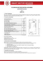
DC BRUSH MOTORCONTROLLER BMSD with RS-485 interface Manual BMSD.002 1. Product designation Brush motor controller BMSD is an electronic device to operate and control DC brush motors with or without a encoder. Motor operation parameters are set either by commands via communication interface RS-485 or via controller’s inputs. Controller is designed to control speed, direction, smooth start and stop of DC brush motors (up to 12A). 2. Technical characteristic Power supply voltage, VDC Max. operation motor curren, A Current protection, A Max. motor voltage Min. nonzero voltage Min. acceleration and deceleration setting, V/sec Max. acceleration and deceleration setting, V/sec External speed adjusting – voltage signal, V External speed adjusting – external potentiometer resistance, kOhm Encoder power supply output, VDC Max. current of encoder sensor, mА Output of encoder sensor Min. value of high-level signal from encoder, V Max. value of low-level signal from encoder, V Min. value of pulse duration of encoder sensor, ms Max. motor stabilized speed, RPM Input signals “DIRECTION” and “START/STOP” parameters - max. resistance, kОm - max. current:, А - signal – clean contact Overall dimensions, mm Environmental Conditions: Ambient Temperature: -25…+50°C Humidity: 90% RH or less upon condition +25°C Condensation and freezing: none Pressure: 650…800 mm of mercury 3. Construction and control elements BMSD is designed as a circuit plate with electronics elements, installed on a plate and covered with a metal case. Besides electronic components, there are indicating and control elements, connection terminals and connectors on the board: • • • • • terminal screws for power supply, brush motor windings and encoder lines, and control circuit connection; “START/STOP” button; Internal preset potentiometers to adjust speed “SPEED”, acceleration “ACCEL” and deceleration “BRAKE”; RS-485 terminals “PE”, “A” and “B”; LED for indication of the controller status. Control inputs: To adjust motor speed internal potentiometer “SPEED” and analog input “(0..5)V” are provided. To adjust acceleration and deceleration internal potentiometers “ACCEL” and “BRAKE” are provided. To change the direction input “REVERSE” is intended. To start or stop motion button and input “START/STOP” are intended. 4. Assembly and connection Please, learn this manual carefully before connection and assembly. Please, wire just when power is off. Do not attempt to change wiring while the power is ON. Please, provide a reliable contact in connection terminals. During wiring, please, observe the polarity and wire management.
Open the catalog to page 1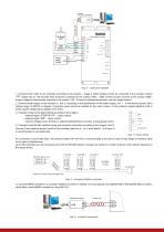
Img. 2 – connection example 1. Connect brush motor to the controller according to the scheme – image 2. Motor phases should be connected to the contacts marked . Signal wire of hall encoder lines should be connected to the contact “HALL”. GND of Hall encoder connects to the contact “GND”, supply voltage for Hall encoder connects to the contact “+5V”. If there is multichannel encoder, use only single channel. 2. Connect power supply to the contacts U+ and U- according to the specification of the power supply unit. - is the electric ground. Input voltage range 10-28VDC is allowed. Connection wires...
Open the catalog to page 2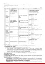
5. Operation Controller BMSD can operate as a standalone unit or be controlled via RS-485 communication interface. Controller modes are performed in the table 2 below. 5.1. Operation modes • As power is on; • As button “START/STOP” pressed or input activated (from modes 2-6); • By command via RS-485 (from modes 2-6). LED indication • Green non-flashing LED light - for all communication address except 0xFF. • Green LED of the controller with 0xFF communication address doesn’t lit LED flashing: 0.2s on – 0.2s off Setting Command via RS-485 2 communicatio (from mode 1) n address Press a button –...
Open the catalog to page 3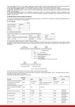
The motor voltage is 0,05* Vsup (5% of supply voltage) at the minimum speed. The motor can completely stop at the minimum speed if the motor model doesn’t accept the voltage. The motor voltage is 0,98* Vsup (98% of supply voltage) at the maximum speed. 4. The motor acceleration depends on the “ACCEL” potentiometer position. The maximum acceleration (minimum acceleration time) corresponds to the end left position - (3Vsup) V/sec. The minimum acceleration (maximum acceleration time) corresponds to the end right position - (3Vsup/8) V/sec. 5. The motor deceleration depends on the “BRAKE” potentiometer...
Open the catalog to page 4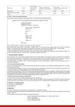
Status scan Start motion Stop motion, go to standby mode Don’t send this byte for 0x50 command Any Status + Counter most significant 4 bits (image 7) Counter least Actual speed significant 8 bits 6.3. CRC – check sum control calculation. The final byte of every command and reply frame is CRC. The CRC calculation algorithm is follow: unsigned char OWI_ComputeCRC8(unsigned char inData, unsigned char seed) { unsigned char bitsLeft; unsigned char temp; for (bitsLeft = 8; bitsLeft > 0; bitsLeft--) { temp = ((seed ^ inData) & 0x01); if (temp == 0) { seed >>= 1; } else { seed ^= 0x18; seed >>= 1; seed...
Open the catalog to page 5All Smart Motor Devices catalogs and technical brochures
 Smart Motor Devices 2021 catalog
14 Pages
Archived catalogs
 Smart Motor Devices 2021
21 Pages
 DC brush motors
4 Pages


- Electromotor
- DC electromotor
- Synchronous motor
- Alternating current motor
- Electric gearmotor
- EC motor
- 24 V motor
- Direct current gear-motor
- Compact electromotor
- 12 V motor
- Stepper motor
- Right angle electric gearmotor
- Coaxial gearmotor
- Planetary gearmotor
- 48 V motor
- DC motor controller
- IP65 motor
- Stepper motor controller
- 36 V motor