- Catalogs
- SmarAct GmbH
- PICOSCALE Interferometer: Measurement of radial run-out and wobble
PICOSCALE Interferometer: Measurement of radial run-out and wobble
1 /4Pages

PICOSCALE Interferometer: Measurement of radial run-out and wobble
1 /4Pages
Catalog excerpts

PICOSCALE Interferometer: Measurement of radial run-out and wobble Abstract The PICOSCALE Interferometer is a displacement sensor with picometer resolution. It may be applied in industrial applications to measure (and eventually correct) the radial run-out of a rotating workpiece or spindle. experiments (Order Code: PS-CTRL-V1.4-HP), which is optimal for low-reflectivity or cylindrical targets. Figure 1. Schematic view of the setup. PICOSCALE sensor heads are used to characterize the motion of a rotating target, which could be a sample holder in synchrotron beamlines. 1. INTRODUCTION In high precision engineering or in synchrotron endstations the precise knowledge of the movement of a rotating target is of crucial interest. Radial run-out and wobble of a rotating spindle may have significant influence on the quality of a workpiece, and thus needs to be reduced. In synchrotron applications, tomography of crystal structures requires even higher precision to accurately position the sample. Thus the run-out and wobble need to be measured accurately. Subsequently, by applying adequate control loops or lookuptables, the rotating target may be kept on the desired trajectory. 2. SETUP The setup of this demonstrator is shown in Figure 2. A polished cylinder (stainless steel) was mounted on a SmarAct xy-stage as well as a rotary stage. The xystage can either be used to set a specific eccentricity to prove the capability of measuring large run-outs of up to 1 mm, or to correct for it. Two line focusing sensor heads (Order Code: PS-SH-L01) were assembled at a specific height with a 90◦ orientation to measure the eccentricity, and a third sensor head was mounted above the second one. The latter pair was used to infer the wobble of the cylinder. A PICOSCALE Controller with increased laser power was used for these Figure 2. Experimental setup. Three PICOSCALE sensor heads with line focused probe beam are targeting a polished cylinder, which is mounted on an xy- and a rotary stage. See text for details. 3. MEASUREMENT PROCEDURE The cylinder was rotated by small increments and at each angle the relative displacement of the target with respect to each sensor head was recorded. In Figure 3 the values for the x- and y-direction are shown. The 90◦ phase shifted signal is (in first order) interpreted as the eccentricity of the sample. The wobble is calculated from the position data of sensor heads 2 and 3. Consequently, a numerical fit is applied to the data that incorporates the wobble of the pin. Thus the effect that each sensor head records the shape of an ellipse instead of a circle is taken into account. The residues from the pin are due to the non-perfect surface of the pin which is overlaid with bearing errors. Figure 4 shows these residues of sensor head 1, for all recorded angles between 0 and 360◦ . The residues are within ±1.5 µm. The line focusing heads allowed to track eccentric movements of up to 1 mm while being insensitive to wobble. Thus, the PICOSCALE c
Open the catalog to page 1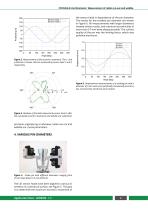
PICOSCALE Interferometer: Measurement of radial run-out and wobble the sensor head in dependence of the pin diameter. The results for the smallest pin diameter are shown in Figure 6. All measurements with larger diameters showed similar results, and maximum eccentricities of more than 0.7 mm were always possible. The surface quality of the pin was the limiting factor, which was polished aluminum. Sensor head 1 Sensor head 2 Figure 3. Measurement of the eccentric movement. The x- and y-direction is shown, that are measured by sensor head 1 and 2, respectively. Figure 4. Residues of the data measured...
Open the catalog to page 2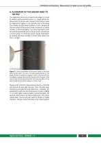
PICOSCALE Interferometer: Measurement of radial run-out and wobble A. ALIGNMENT OF THE SENSOR HEAD TO THE PIN The alignment of the senor head to the target is crucial to obtain optimal performance, i.e. large lateral displacements of the pin with respect to the sensor head. As depicted in Figure 7, the cylinder lens is focusing the initially circular beam profile to a line. Directly at the exit pupil of the sensor head, the beam is nearly circular. In the focal plane, it is a thin line which must be oriented perpendicular to the pin’s axis. Sometimes it can be easier to check the sensor heads...
Open the catalog to page 3
Germany SmarAct GmbH Schuette-Lanz-Strasse 9 26135 Oldenburg Germany T: +49 441 - 800 879 0 Email: [email protected] www.smaract.com China Dynasense Photonics 6 Taiping Street Xi Cheng District, Beijing, China T: +86 10-835 038 53 Email: [email protected] www.dyna-sense.com France SmarAct GmbH Schuette-Lanz-Strasse 9 26135 Oldenburg Germany T: +49 441 - 800 879 956 Email: [email protected] www.smaract.com Natsu Precision Tech Room 515, Floor 5, Building 7, No.18 East Qinghe Anning Zhuang Road, Haidian District Beijing, China T: +86 18-616 715 058 Email: [email protected] www.nano-stage.com...
Open the catalog to page 4All SmarAct GmbH catalogs and technical brochures
 CATALOG 2025
192 Pages
 SMARPOD P-SLC-24
2 Pages
 PLF3232-xy.60
1 Page
 Catalog 22
182 Pages
 CGO-60.5
2 Pages
 CLS-3232
1 Page
 CHS-3232-1D-5
2 Pages
 SR-1908
1 Page
 CLL42
CLL421 Page
 SmarAct Catalog 20
212 Pages
 DLS-3232
1 Page
 SR-2812-CR
1 Page
 CHS-5237-1D10N-10
1 Page
 SR-3211
1 Page
 SLS-3232
1 Page
 Sensor Head C03
4 Pages
 Sensor Head F01
4 Pages


Archived catalogs
 Sensor Head C01
4 Pages


- SmarAct automation software
- Analysis software solution
- SmarAct positioning stage
- Digital I/O
- Incremental encoder
- Process software
- Control software
- SmarAct linear positioning stage
- Analog I/O
- 3D software solution
- SmarAct interface software
- Measurement software
- Motorized positioning table
- Temperature controller
- SmarAct precision positioning stage
- Visualization software solution
- Motor controller
- Programming software
- Development software