
- Catalogs
- SKF Lubrication Systems Germany GmbH
- Product Series OLA, MV and 161


- Company
- Products
- Catalogs
- News & Trends
- Exhibitions
Product Series OLA, MV and 161

Product Series OLA, MV and 161
SKF Oil+Air lubrication units and mixing valves are designed for centralized lubrication systems, primarily used in mechanical engineering for bearing lubrication, especially spindle bearings. They offer high availability, low wear, and long service life. These units can be configured for various applications, including chain, gear train, and process oiling.
- Improved machining performance due to higher speed factors.
- Continuous lubricant supply enhances dependability and protects against contamination.
- Reduced lubricant consumption by approximately 90% compared to oil lubrication.
- Bearing lubrication, especially spindle bearings.
- Chain and gear train lubrication.
- Slideway lubrication and process oiling.
The product selection table provides details on various SKF Oil+Air lubrication units and mixing valves, including material, actuating pressure, and metered quantities.
These systems use a metered quantity of oil drawn into streaks by a continuous air flow, transported to the lubrication point. The system prevents contamination ingress and does not form an oil mist. Components include gear pump units, mixing valves, air control valves, and oil-streak sensors.
Oil+air lubrication is suitable for high-speed applications where conventional systems fail due to friction-related losses. It allows precise metering of lubricant quantities, unlike oil-mist lubrication. Permanent grease lubrication has lower speed limits compared to oil+air lubrication.
The required lubricant amount depends on bearing type and dimensions. The formula Q = w × d × B is used to calculate approximate oil requirements, but empirical determination is often necessary.
Compressed air must be dry and filtered, with a filter rating of <= 5 μm. Suitable oils are ISO grades VG 32 to VG 100, avoiding those with molybdenum disulfide additives.
Lubricant feeding depends on bearing type and design. For single-row bearings, lubricant should be introduced from the side at the inner ring level. For double-row bearings, it should be introduced at the outer ring raceway level. Transparent plastic secondary lines are recommended for visual assessment of lubricant transport.
The SKF Oil+Air lubrication systems are designed to ensure efficient lubrication of bearings. Key components include a lubricant reservoir, secondary lines, and oil-streak sensors for monitoring lubricant flow. The systems can be configured with various gear pump units, air filters, oil filters, and pressure switches, depending on the application requirements.
The document outlines the proper installation of secondary lines, emphasizing the importance of maintaining a horizontal or slightly inclined position to ensure consistent lubricant supply. It advises against abrupt changes in line cross-sections and recommends using SKF oil-streak sensors for continuous monitoring.
The configurator section provides a detailed breakdown of the order coding system for SKF Oil+Air lubrication units. It includes options for the number of metering points, design of gear pump units, air and oil filter configurations, and pressure switch settings. An example order code is provided to illustrate the selection process.
The document includes technical specifications for the gear pump units, including delivery rates, operating pressures, and ambient temperature ranges. It also details the electrical specifications for the motor and control units, as well as the characteristics of the oil and air filters.
The SKF Oil+Air mixing valves are available in various designs, with options for adjustable or non-adjustable air metering. The valves can accommodate up to eight secondary line connections, with metered quantities ranging from 0.01 to 0.16 cm3 per cycle. The document provides dimensions and mounting instructions for these valves.
For optimal performance, it is recommended that changes to metered quantities be performed by authorized SKF personnel. The document also highlights the importance of proper wiring and configuration to prevent damage to components.
1. Connection for compressed air is either G1/2 or G3/4 depending on the design.
2. Actuating pressure for air ranges from 3–10 bar, and for oil, it ranges from 12–45 bar.
3. Operating viscosity is between 20–1,500 mm2/s.
4. Pumped medium includes mineral or synthetic oil compatible with NBR elastomers.
5. Mounting position is as illustrated in the document.
1. Metered quantities range from 0.03 to 0.10 cm3/cycle depending on the order number.
2. Metering is replaceable and can be adjusted based on lubrication needs.
1. SKF Oil+Air mixing valves are available without metering and can be grouped for multiple lubrication points.
2. The lubricant supply connection has a counterbore for a solderless tube union for tube ∅4 mm.
3. Additional mixing valves are required for each additional lubrication point.
1. SKF Oil+Air flow dividers distribute oil+air flows to 2–6 lubrication points.
2. Uniform distribution requires no back pressure on the outlets and consistent secondary line lengths.
1. Includes hose coils, nozzles, pressure switches, and various connectors.
2. Specific order numbers are provided for different configurations and requirements.
1. Detailed list of spare parts with order numbers and designations.
2. Includes gear pump units, oil+air metering units, filter elements, and pressure switches.
1. SKF and Lincoln lubrication systems are not approved for use with gases, liquefied gases, pressurized gases in solution, and fluids with a vapor pressure exceeding normal atmospheric pressure by more than 0.5 bar at their maximum permissible temperature.
Catalog excerpts

SKF Oil+Air Lubrication Units and Mixing Valves Product Series OLA, MV and 161 For use in SKF Oil+Air Centralized Lubrication Systems
Open the catalog to page 1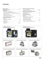
Contents Product overview 2 Product selection table 3 Fundamentals SKF Oil+Air lubrication systems 4 Components of oil+air lubrication systems 4 Principles of oil+air lubrication - example: rolling bearings 5 Lubricant quantities 5 Requirements for compressed air 6 Requirements for lubricant 6 Lubricant feed lines (criteria, bearing type) 7 SKF Oil+Air lubrication units Designs 8 Configurator, order example 9 Dimensions 10 Technical data 11 Hydraulic layouts 12 Spare parts 23–24 SKF Oil+Air lubrication unit OLA8-1B6BB (maximum equipment level) SKF Oil+Air mixing valves with metering MV20x-1 /...
Open the catalog to page 2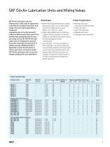
SKF Oil+Air Lubrication Units and Mixing Valves SKF Oil+Air lubrication units are employed for a wide range of applications in the field of centralized lubrication technology The main field of application is mechanical engineering due to the high demands made on a defined lubrication system that provides high availability with low wear and a long service life SKF Oil+Air lubrication units are employed for bearing lubrication, especially the lubrication of spindle bearings Additional fields of application include the lubrication of chains, gear trains, and process oiling SKF Oil+Air lubrication...
Open the catalog to page 3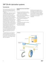
SKF Oil+Air lubrication systems Fundamentals Oil+air lubrication systems SKF Oil+Air lubrication systems are employed for bearing lubrication, especially the lubrication of spindle bearings Additional fields of application include the lubrication of chains, gear trains, and process oiling Oil+air lubrication is distinguished by the fact that a metered quantity of oil is drawn into streaks in a lubrication line by a continuous air flow (compressed air) and is transported in the direction of the compressed air flow along the tube wall and to the lubrication point A lubrication unit, a progressive...
Open the catalog to page 4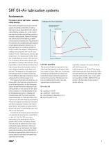
SKF Oil+Air lubrication systems Fundamentals Principles of oil+air lubrication - example: rolling bearings Many fields of engineering require that the speeds of spindles and shafts on rolling bearings increase beyond the limits cited in rolling bearing catalogs, e g in the case of bearings for grinding and milling spindles to increase cutting speeds Beyond the design and construction of the bearing, another critical aspect of meeting this requirement is the selection of a suitable lubrication system Conventional lubrication systems (e g oil bath lubrication or circulating-oil lubrication), for...
Open the catalog to page 5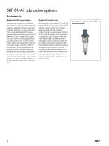
SKF Oil+Air lubrication systems Fundamentals Requirements for compressed air Compressed air must be dry and filtered; filter rating of <= 5 μm A conventional water separator, preferably with semi-automatic emptying, is sufficient for water separation The quantity of air required for faultless transport of the oil in tubing with an internal diameter of 2 3 mm ranges from roughly 1 000 to 1 500 I/h This value applies to oil viscosity classes ISO VG 32 to ISO VG 100 Higher values must be assumed in the case of oils with a higher viscosity or different adhesiveness The air pressure has to be adjusted...
Open the catalog to page 6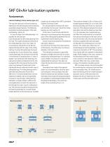
SKF Oil+Air lubrication systems Fundamentals Lubricant feeding (criteria, bearing type, etc ) The way the lubricant is fed to the bearing depends on the bearing type and the bearing assembly’s design features The following illustrations provide examples of the lubricant feeding († Fig 1) In case of single-row rolling bearings, it is possible for the lubricant to be introduced into the rolling bearing from the side The nozzle should be at the level of the rolling bearing’s inner ring Under no circumstances should the oil+air flow be aligned directly with the cage of the rolling bearing If using...
Open the catalog to page 7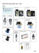
SKF Oil+Air lubrication unit – OLA Designs Note Maximum design Minimal design Gear pump unit with control unit Gear pump unit without control unit This page shows possible designs of the oil+air lubrication units The configurator on the following page allows the functional specification of a unit with associated order number Oil filters with monitoring Oil filters without monitoring Pressure switch for minimum air pressure Compressed air control valve with air filter and water seperator Mixing valve with metering 3/2 directional air control valve Counterbore for solderless tube union for tube...
Open the catalog to page 8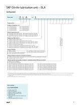
SKF Oil+Air lubrication unit – OLA Configurator Order coder Product series Number of metering points 5 = 5 metering points 1 = 1 metering point 2 = 2 metering points 6 = 6 metering points 7 = 7 metering points 3 = 3 metering points 8 = 8 metering points 4 = 4 metering points Design of oil filter X = without oil filter A = with 3 µm oil filter, without monitoring B = with 3 µm oil filter, with monitoring Design of air filter / valve 1) 0 = without air filter, without valve 1 = without air filter, with 3 / 2 directional control, 24 V DC 2 = without air filter, with 3 / 2 directional control valve,...
Open the catalog to page 9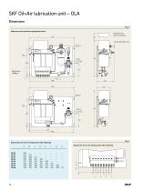
SKF Oil+Air lubrication unit – OLA Dimensions Fig 3 Maximum and minimum equipment levels 507 Clearance for cover mounting Dimensions of oil+air mixing valve with metering A OLA1 OLA2 OLA3 OLA4 OLA5 OLA6 OLA7 OLA8
Open the catalog to page 10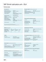
SKF Oil+Air lubrication unit – OLA Technical data Oil pressure switch (included in gear pump unit) Gear pump unit 1) Delivery rate of unit 2) Number of metering points Max operating pressure Ambient temperature Pumped medium 0,2 l / min 1 to 8 (>8 on request) 30 bar +10 to +40 °C Mineral or synthetic oil, compatible with NBR elastomersn Operating viscosity Rated capacity of lubricant reservoir Lubricant reservoir material Protection class Pressure relief valve Thermal circuit breaker Duty type (per VDE 0530) Mounting position Polyamide (PA6) IP54 Included Included Standard design: S3, ON-time...
Open the catalog to page 11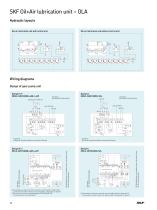
SKF Oil+Air lubrication unit – OLA Hydraulic layouts Oil+air lubrication unit with control unit Oil+air lubrication unit without control unit Wiring diagrams Design of gear pump unit Design E / F MKU2-12BC11000+428 /+429 1) Connected by customer to internal control unit (if present) or external PLC Compressed-air valve minimum air pressure (DL), compressed-air valve Y1 2) The control unit can be switched between 230 V and 115 V AC The pump motor is not switchable! 1) Connected by customer to internal control unit (if present) or external PLC Compressed-air valve minimum air pressure (DL), compressed-air...
Open the catalog to page 12All SKF Lubrication Systems Germany GmbH catalogs and technical brochures
 SKF Compact greaser
8 Pages
 Pump unit PPS30
4 Pages
 ECP Product brochure
8 Pages
 Pulse meter IPM
4 Pages
 Product series 143 brochure
24 Pages
 Wire rope lubrication system
8 Pages
 Single- and Multi-circuit Pumps
16 Pages
 LubriLean brochure
4 Pages
 1154 flyer
2 Pages
 EDL1 product brochure
4 Pages
 DSA product brochure
4 Pages
 DSC3 product brochure
4 Pages
 DSB product brochure
4 Pages
 HCC product brochure
2 Pages
 LMC 301 product brochure
8 Pages
 SFZM product brochure
4 Pages
 SP/SMB14 product brochure
8 Pages
 SP/SMB13 product brochure
8 Pages
 SMBM product brochure
18 Pages
 Safeflow product brochure
4 Pages
 SMT 1 product brochure
8 Pages
 LP2 / LPC product brochure
8 Pages
 PSG product brochure
36 Pages
 VP product brochure
20 Pages
 VPK product brochure
20 Pages
 VPB product brochure
12 Pages
 SPVS product brochure
8 Pages
 SKF Maxilube Solution
8 Pages
 SGA/SG product brochure
6 Pages
 SLC product brochure
12 Pages
 SL-6 product brochure
4 Pages
 SL-32HV product brochure
2 Pages
 310 series product brochure
4 Pages
 BPH product brochure
4 Pages
 Lubrigun product brochure
15 Pages
 EOP2 product brochure
2 Pages
 MPB product brochure
2 Pages
 FK product brochure
12 Pages
 VectoLub product brochure
30 Pages
 Gear Pump Units brochure
12 Pages
 P502 product brochure
2 Pages
 LubriLean product brochure
16 Pages
 P603S product brochure
8 Pages
 P212 product brochure
2 Pages
 P205/ P215 product brochure
2 Pages
 MKx series product brochure
24 Pages
 CLK product brochure
8 Pages
 Gear wheel indicator SFZM
4 Pages
 Oil conditioning unit OCU
4 Pages
 LFC 5000
4 Pages
 SSV-D
SSV-D2 Pages
 Improved Centro-Matic SL-11
12 Pages
 SL-V XL
4 Pages
 12-volt Reel 'n F
2 Pages
 New 90-lb. Reservoir
12 Pages
 HTL 429
4 Pages
 Lincoln
8 Pages
 AC FlowMaster
12 Pages
 EOS
EOS2 Pages
 LFR Series
4 Pages
 Hand Vacuum Pumps
6 Pages
 Pumps PMV Pump Family
16 Pages


