
- Catalogs
- SKF Lubrication Systems Germany GmbH
- CLK installation and operation manual


- Company
- Products
- Catalogs
- News & Trends
- Exhibitions
CLK installation and operation manual

CLK installation and operation manual
This document serves as an installation and operation manual for the CLK lubrication system, an airless oil projection system for conveyor roller chain lubrication. Issued in June 2021, it complies with the EU Machine Directive 2006/42/CE, ensuring safe and effective use.
The manual is copyrighted and must remain near the equipment for reference. Unauthorized reproduction is prohibited. The manufacturer is SKF France SAS, with service support from SKF Lubrication Systems Germany GmbH.
SKF offers training courses for safety and efficiency. Warranty details are available in the General Conditions of Sales on the SKF website.
Safety is crucial, with specific instructions for handling, assembly, and operation. Only qualified personnel should perform these tasks, and safety devices must remain intact.
Guidelines for selecting and using approved lubricants are provided, emphasizing environmental considerations and potential dangers.
The system's design, versions, and construction are detailed, explaining its function and operational principles.
Technical specifications ensure proper installation and operation.
Instructions for safe transport, delivery, and storage are included to maintain system integrity.
Comprehensive steps for installation, including positioning, hydraulic, and electrical connections, are outlined to ensure correct setup.
Guidelines for system commissioning, including control unit setup, bleeding, and reservoir filling, are provided to ensure readiness for operation.
Regular maintenance procedures and troubleshooting for common failures are described to maintain system performance.
Instructions for temporary and permanent shutdowns are included, along with information on spare parts to ensure system longevity.
- Electric Shock Hazard: Electrical connections must be made by qualified personnel following local regulations. Ensure products are disconnected from power before maintenance.
- System Pressure Hazard: Depressurize the product before assembly, maintenance, or repair.
- Inform all relevant personnel before starting work and ensure moving parts are immobilized.
- Work on electrical components only with voltage-insulated tools and ensure proper grounding.
- Use suitable lifting gear for heavy parts and avoid mixing up disassembled parts.
- The product is designed for lubricating moving conveyor chains. It should not be used in explosive atmospheres or for transporting hazardous substances without proper precautions.
- Only use lubricants approved by SKF. Mixing different lubricants can cause damage.
- Lubricants are harmful to the environment and must be handled according to safety data sheets and local regulations.
- The CLK lubrication system includes a central unit with an electromagnetic pump and control unit, designed for airless oil projection onto moving chains.
- Lubrication is achieved through projection nozzles, with precise doses controlled by a proximity sensor.
- The system operates with a flow rate of 30 or 60 mm3 per stroke, with a maximum delivery pressure of 100 bar.
- Operating temperature ranges from -25 to +200°C, with a reservoir capacity of 7.5 liters.
- Number of nozzles: 2
- Accessories: Holder and fittings
- Sensor: Inductive proximity switch, 3-wire DC PNP, NO output function
- Operating voltage: 10 to 36 V DC
- Nominal range: 5 mm
- Operating temperature: -40 to +85 °C
- Pipe: Length 2.5 or 5 m, Diameter 4 mm, Material: stainless steel, PTFE pipe holder
- For other viscosities, contact SKF Service Centre.
Transport: Products are packaged per recipient country regulations and DIN ISO 9001. Handle with care to avoid mechanical impacts. No transport restrictions.
Delivery: Check products for damage upon receipt and verify delivery completeness.
Storage: Store in a dry, dust-free, well-ventilated area. Max storage time: 24 months. Avoid direct sunlight and heat sources. Protect uncoated metal surfaces from corrosion.
General: Installation should be performed by qualified experts. Remove packaging and safety devices before installation.
Position: Mount system to avoid humidity and vibrations. Ensure accessibility and sufficient air circulation.
Installation: Avoid damaging existing lines and components. Maintain safety distances and follow local guidelines.
Central Unit Installation: Mount on a wall with appropriate screws and ensure free space for maintenance.
Nozzle Installation: Place above chain rollers, adjust nozzle heads for alignment, and secure properly.
Proximity Sensor Installation: Mount on the same support as nozzles, adjust position, and ensure vertical alignment with lubrication points.
Hydraulic: Connect lubrication line to central unit without applying force. Use crimp ring fittings for connections.
Electrical: Connect power supply, proximity sensor, and fault output to the central unit. Follow local regulations and ensure correct voltage.
General: Regularly check lubricant transport and reservoir levels. Use clean lubricants and avoid mixing different types.
Control Unit: Features an integrated command and control unit with a user-friendly interface. Configure lubrication mode, cycle time, and other settings through the control unit menus.
The document outlines three lubrication modes: cyclic, semi-automatic, and continuous. Cyclic lubrication requires setting a cycle time between 0h 01min and 999h 59min. Semi-automatic lubrication is manually triggered by the user, while continuous lubrication operates as long as the system is powered and the chain is running.
The control unit allows adjustments for lubrication mode, number of axes, pitch jump, fine adjustment of nozzle position, and pump control. The number of lubrication points can be set between 0 and 9,999. Pitch jump allows lubrication frequency adjustment, with a default value of 1. Fine adjustment involves modifying the nozzle position relative to lubrication points. Pump control can be set to DIRECT or ADAPTIVE, depending on chain speed.
Bleeding the system is essential before commissioning and after maintenance. The process involves removing air bubbles from the lubrication lines. Reservoir filling requires cleaning the cap and using appropriate lubricants.
Before activation, all connections should be checked. The system operates according to user configuration, with progress displayed on the central unit. Maintenance involves checking joints and connections, cleaning the pump with appropriate agents, and ensuring the use of compatible lubricants.
Tables provide solutions for common issues such as low oil levels, sensor faults, and system malfunctions. Troubleshooting involves checking power supply, lubricant levels, and component conditions.
Temporary and permanent shutdown procedures are outlined, with emphasis on legal guidelines for disposal. Only original SKF spare parts should be used, and alterations to the product are prohibited.
This section provides detailed information on spare parts and accessories for various CLK kits, including specifications for proximity switches, tubes, and other components. It also includes important usage information for SKF and Lincoln lubrication systems.
- CLK-260R-100: Includes central unit, double nozzle, proximity switch Ø12, power supply connection kit, fault output connector, and various support and tube components.
- CLK-460R-110: Features a high-temperature proximity switch Ø18, central unit, double nozzle, and similar accessories as CLK-260R-100.
- CLK-430R-101: Contains a simple nozzle, standard proximity switch Ø12, and similar components as previous kits.
- CLK-430R-121: Includes a simple nozzle, standard proximity switch Ø8, and similar components as previous kits.
Catalog excerpts

Installation and operation manual CLK lubrication system Airless oil projection system for conveyor roller chain lubrication Form number Read manual prior to installation or use of this product. Keep manual nearby for future reference.
Open the catalog to page 1
Training courses In order to provide a maximum of safety and economic viability, SKF carries out detailed training courses. It is recommended that the training courses are attended. For more information please contact the SKF Service Center or the local SKF representative. In accordance with the EU Machine Directive 2006/42/CE, the installation and operation instructions are an integral part of a lubrication system and must be kept close to the equipment for future reference. The installation and operation instructions were drafted in compliance with the applicable standards and rules governing...
Open the catalog to page 2
Contents Imprint . . . . . . . . . . . . . . . . . . . . . . . . . . . . . . . . . . . . . . . . . . . . . . . . . . . . . . . . . . . . . . . . . Service . . . . . . . . . . . . . . . . . . . . . . . . . . . . . . . . . . . . . . . . . . . . . . . . . . . . . . . . . . . . . . . . . Training courses . . . . . . . . . . . . . . . . . . . . . . . . . . . . . . . . . . . . . . . . . . . . . . . . . . . . . . . . Warranty . . . . . . . . . . . . . . . . . . . . . . . . . . . . . . . . . . . . . . . . . . . . . . . . . . . . . . . . . . . . . . Disclaimer . . . . . . . . . . . . . . . . . . . . ....
Open the catalog to page 3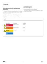
General • rotational direction arrows • fluid connection labels, etc. Meaning of symbols and corresponding information must be respected and remain perfectly legible. It is essential to read these instructions thoroughly and to respect the safety instructions given. In this manual, the symbols and safety wordings shown on this page are intended to communicate a particular risk to persons, material assets, or the environment. All safety instructions must be respected by person exposed to these risks. The safety instructions must be communicated to all other persons. Instructions attached directly...
Open the catalog to page 4
Information concerning the EC Declaration of Incorporation EC Declaration of Incorporation in accordance with EC-Machinery Directive 2006/42/EC, Appendix II Part B The manufacturer SKF France SAS, 204, Bld Charles de Gaulle, B.P. 239 – 37540 St-Cyr-sur-Loire – FRANCE, declares herewith the conformity of the partly completed machine Designation: Type: Order No.: Year of construction: Grease injection lubrication system for chains CLK see ID plate see ID plate with the following essential health and safety requirements of the EC Machinery Directive 2006/42/EC when released on the market. 1.1.2...
Open the catalog to page 5
1.3 Qualified technical personnel Only qualified technical personnel may install, operate, maintain, and repair the products described in the manual. Qualified technical personnel are persons who have been trained, assigned and instructed by the operator of the installation. These persons are considered capable of such tasks due to their education, training, and experience with valid standards, conditions, accident prevention regulations in effect, and installation conditions. They should be able to carry out the required tasks and to recognize – and thus avoid – any dangers that might otherwise...
Open the catalog to page 6
1.5 System pressure hazard points. Product may only be used following the specifications, technical data and limits stated in this manual. Other use or use beyond this purpose is considered unintended. System pressure The product is pressurized during operation. The product must therefore be depressurized before starting assembly, maintenance, or repair work A usage of the product differing from the aforementioned conditions and stated purpose is strictly prohibited. Particularly prohibited are: • use in an explosive atmosphere (according to guideline ATEX 2014/34/EU) • use without integrated...
Open the catalog to page 7
NOTE The manufacturer of the chain to be lubricated will specify the lubricant requirements for each point to be lubricated. You must make sure that the required quantity of lubricant is provided to the relevant lubricating point. If a lubricating point is insufficiently lubricated, the bearing may become damaged or jammed. 2.1 General NOTE All SKF products must only be used for their intended purpose and in accordance with the specifications of the installation instructions for the product in question. While the machinery/bearing manufacturer usually specifies lubricants, it is the owner/operator...
Open the catalog to page 8
2.5 Danger relating to lubricants CAUTION Different lubricants must not be mixed together. Doing so can cause damage and require extensive cleaning of the products/centralized lubrication system. To prevent confusion, we recommend that you attach information indicating the lubricant to be used on the lubricant reservoir. CAUTION Centralized lubrication systems must be absolutely leakfree. Leaking centralized lubrication systems can cause a slip hazard. When performing installation, maintenance, and repairs test the centralized lubrication system for leaks. Leaky parts of the centralized lubrication...
Open the catalog to page 9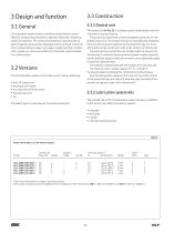
3.3.1 Central unit The central unit († fig. 1) is a compact group comprising a reservoir mounted on a pump housing. The pump housing houses an electromagnetic pump and an integrated control unit. The control unit can be controlled and monitored from the control panel located on the housing front side. For more information on the control unit, refer to the section 6.2 Control unit. The unit electrical connections are located under the rear part of the housing. It comprises three connectors (power supply, proximity sensor and fault outputs). A fourth connector can be optionally added to check the...
Open the catalog to page 10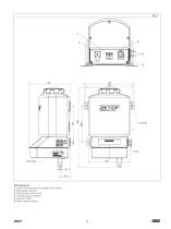
CLK central unit 1 Level-contact connector (according to the version) 2 Fault output connector 3 Control panel of control unit 4 Proximity sensor connector 5 Lubricant outlets 6 Power supply connector
Open the catalog to page 11
Fig. 2 Projection nozzles with proximity sensor mounted on a support Connector M12 (with 5 m cable) Inductive proximity sensor
Open the catalog to page 12All SKF Lubrication Systems Germany GmbH catalogs and technical brochures
 SKF Compact greaser
8 Pages
 Pump unit PPS30
4 Pages
 ECP Product brochure
8 Pages
 Pulse meter IPM
4 Pages
 Product series 143 brochure
24 Pages
 Wire rope lubrication system
8 Pages
 Single- and Multi-circuit Pumps
16 Pages
 LubriLean brochure
4 Pages
 1154 flyer
2 Pages
 EDL1 product brochure
4 Pages
 DSA product brochure
4 Pages
 DSC3 product brochure
4 Pages
 DSB product brochure
4 Pages
 HCC product brochure
2 Pages
 LMC 301 product brochure
8 Pages
 SFZM product brochure
4 Pages
 SP/SMB14 product brochure
8 Pages
 SP/SMB13 product brochure
8 Pages
 SMBM product brochure
18 Pages
 Safeflow product brochure
4 Pages
 SMT 1 product brochure
8 Pages
 LP2 / LPC product brochure
8 Pages
 PSG product brochure
36 Pages
 VP product brochure
20 Pages
 VPK product brochure
20 Pages
 VPB product brochure
12 Pages
 SPVS product brochure
8 Pages
 SKF Maxilube Solution
8 Pages
 SGA/SG product brochure
6 Pages
 SLC product brochure
12 Pages
 SL-6 product brochure
4 Pages
 SL-32HV product brochure
2 Pages
 310 series product brochure
4 Pages
 BPH product brochure
4 Pages
 Lubrigun product brochure
15 Pages
 EOP2 product brochure
2 Pages
 MPB product brochure
2 Pages
 FK product brochure
12 Pages
 VectoLub product brochure
30 Pages
 Gear Pump Units brochure
12 Pages
 P502 product brochure
2 Pages
 LubriLean product brochure
16 Pages
 P603S product brochure
8 Pages
 P212 product brochure
2 Pages
 P205/ P215 product brochure
2 Pages
 MKx series product brochure
24 Pages
 Product Series OLA, MV and 161
28 Pages
 CLK product brochure
8 Pages
 Gear wheel indicator SFZM
4 Pages
 Oil conditioning unit OCU
4 Pages
 LFC 5000
4 Pages
 SSV-D
SSV-D2 Pages
 Improved Centro-Matic SL-11
12 Pages
 SL-V XL
4 Pages
 12-volt Reel 'n F
2 Pages
 New 90-lb. Reservoir
12 Pages
 HTL 429
4 Pages
 Lincoln
8 Pages
 AC FlowMaster
12 Pages
 EOS
EOS2 Pages
 LFR Series
4 Pages
 Hand Vacuum Pumps
6 Pages
 Pumps PMV Pump Family
16 Pages


