
- Catalogs
- SKF Lubrication Systems Germany GmbH
- Circulating Lubrication Systems (Oil) Screw-in restrictors, metering valve distributors, flow volume dividers


- Company
- Products
- Catalogs
- News & Trends
- Exhibitions
Circulating Lubrication Systems (Oil) Screw-in restrictors, metering valve distributors, flow volume dividers

Circulating Lubrication Systems (Oil) Screw-in restrictors, metering valve distributors, flow volume dividers
- Screw-in Restrictors: Used for delivering small oil amounts, sensitive to dirt, and require clean oil with a recommended filter size of 10 µm.
- Metering Valve Distributors: Allow for adjustable flow rates per lubrication point, suitable for varying oil needs.
- Flow Volume Dividers: Divide the main oil flow into parallel flows, independent of system pressure and viscosity.
Catalog excerpts

Circulating Lubrication Systems (Oil) Screw-in restrictors, metering valve distributors, flow volume dividers Screw-in restrictor A continuous flow of oil is often necessary for the lubrication or cooling of machines or systems requiring large amounts of oil. This flow is produced by gear, gerotor, vane and piston pumps and then distributed to meet the needs of the individual lube points. Metering valve distributor The system is very simple if there is only one lube point to be supplied. But if the lubricant is to be delivered to a number of lube points in equal quantities or certain proportions, there are several possibilities entailing different expenses and effects. Flow volume divider SP/SMT (cf. leaflet 1-5017-EN) If must be remembered that circulating lubrication systems require an oil return line from the lube points to the oil reservoir.Adequate filtering of the oil must be provided. Restrictors, especially for small amounts of oil, are sensitive to dirt.
Open the catalog to page 1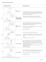
Circulating Lubrication Systems (Oil) System description Distribution systems 1b Screw-in restrictors and adjustable metering valve distributors 1c Flow monitors with choke A pump supplies a network of lines connected to all the lube points via manifolds and branch lines. The quantity is apportioned in inverse proportion to the resistance of the restrictor tubes, screw-in restrictors or metering valve distributors. Screw-in restrictors can be installed on manifolds (cf. leaflet 1-0103-EN) or screwed directly into the threads of the lube points. System similar to 1b, but the interchangeable metering...
Open the catalog to page 2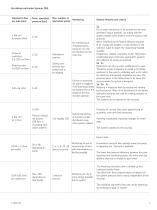
Circulating Lubrication Systems (Oil) Volumetric flow per lube point Screw-in restrictors: 0.2–230 cm³/min Perm. operating pressure [bar] Max. number of Monitoring lubrication points Metering valve 0–2000 cm³/min Tubing cross sections and pump have to be adapted. 1a For an even distribution of oil, provide for the most symmetric layout possible. Lay tubing with the largest possible cross sections from the pump to the junctions. When individual points require different amounts No monitoring of of oil, change the lengths or cross sections of the individual points, restrictor tubes to obtain the...
Open the catalog to page 3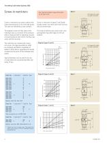
Circulating Lubrication Systems (Oil) Screw-in restrictors See important product usage information on the back cover. Screw-in restrictors are used to deliver relatively small amounts of oil to the lube points. The sizes are identified by code numbers. Screw-in restrictors of types C and D additionally contain one check valve each that can help to prevent leaks. The diagrams show the flow rates of the individual sizes as a function of the pressure and as measured with an operating viscosity of oil amounting to 140 mm2/s. The flow rate varies with the viscosity. Type A Port tapped for solderless...
Open the catalog to page 4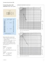
Circulating Lubrication Systems (Oil) Connecting piece with restrictor (compl. with washer) Nomograph for determination of restrictor size Code No. Ports tapped for solderless tube connection to DIN 2353 (cutting sleeve) Lubricant quantity Q [cm³/min] Code No. 60 61 62 Example 2 required: Q = 260 cm³/min, given: eff = 480 mm2/s, p = 8 bar Result: restrictor size No. 80 Example 1 required: Q = 36 cm³/min, given: eff = 280 mm2/s, p = 7 bar Result: restrictor size No. 60 (borderline case) Determining the restrictor size 1. Draw a straight line along the index lines through point Q eff. 2. Determine...
Open the catalog to page 5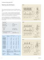
Circulating Lubrication Systems (Oil) Metering valve distributors These metering valve distributors are used if an infinitely variable adjustment of the flow rate per lube point is required – even at a later date. In the case of type A – for flow rates within the drop-feed range – knurled lock nuts and knurled screws are provided for adjustment purposes. It is necessary to provide for a sufficiently large drain-off in order to maintain a free fall of drops in the sight-glass. In the case of types B and C, the continuous flow rate is adjusted after the upper hexagonal lock nut is loosened. Spring-loaded...
Open the catalog to page 6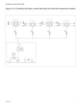
Circulating Lubrication Systems (Oil) Layout of a circulating lubrication system (printing machine) with progressive feeders
Open the catalog to page 7
Order No. 1-5006-EN Subject to change without notice! (11/2015) Important information on product usage All products from SKF may be used only for their intended purpose as described in this brochure and in any instructions. If operating instructions are supplied with the products, they must be read and followed. Not all lubricants are suitable for use in centralized lubrication systems. SKF does offer an inspection service to test customer supplied lubricant to determine if it can be used in a centralized system. SKF lubrication systems or their components are not approved for use with gases,...
Open the catalog to page 8All SKF Lubrication Systems Germany GmbH catalogs and technical brochures
 SKF Compact greaser
8 Pages
 Pump unit PPS30
4 Pages
 ECP Product brochure
8 Pages
 Pulse meter IPM
4 Pages
 Product series 143 brochure
24 Pages
 Wire rope lubrication system
8 Pages
 Single- and Multi-circuit Pumps
16 Pages
 LubriLean brochure
4 Pages
 1154 flyer
2 Pages
 EDL1 product brochure
4 Pages
 DSA product brochure
4 Pages
 DSC3 product brochure
4 Pages
 DSB product brochure
4 Pages
 HCC product brochure
2 Pages
 LMC 301 product brochure
8 Pages
 SFZM product brochure
4 Pages
 SP/SMB14 product brochure
8 Pages
 SP/SMB13 product brochure
8 Pages
 SMBM product brochure
18 Pages
 Safeflow product brochure
4 Pages
 SMT 1 product brochure
8 Pages
 LP2 / LPC product brochure
8 Pages
 PSG product brochure
36 Pages
 VP product brochure
20 Pages
 VPK product brochure
20 Pages
 VPB product brochure
12 Pages
 SPVS product brochure
8 Pages
 SKF Maxilube Solution
8 Pages
 SGA/SG product brochure
6 Pages
 SLC product brochure
12 Pages
 SL-6 product brochure
4 Pages
 SL-32HV product brochure
2 Pages
 310 series product brochure
4 Pages
 BPH product brochure
4 Pages
 Lubrigun product brochure
15 Pages
 EOP2 product brochure
2 Pages
 MPB product brochure
2 Pages
 FK product brochure
12 Pages
 VectoLub product brochure
30 Pages
 Gear Pump Units brochure
12 Pages
 P502 product brochure
2 Pages
 LubriLean product brochure
16 Pages
 P603S product brochure
8 Pages
 P212 product brochure
2 Pages
 P205/ P215 product brochure
2 Pages
 MKx series product brochure
24 Pages
 Product Series OLA, MV and 161
28 Pages
 CLK product brochure
8 Pages
 Gear wheel indicator SFZM
4 Pages
 Oil conditioning unit OCU
4 Pages
 LFC 5000
4 Pages
 SSV-D
SSV-D2 Pages
 Improved Centro-Matic SL-11
12 Pages
 SL-V XL
4 Pages
 12-volt Reel 'n F
2 Pages
 New 90-lb. Reservoir
12 Pages
 HTL 429
4 Pages
 Lincoln
8 Pages
 AC FlowMaster
12 Pages
 EOS
EOS2 Pages
 LFR Series
4 Pages
 Hand Vacuum Pumps
6 Pages
 Pumps PMV Pump Family
16 Pages


