Group: SKF

Catalog excerpts

SP/SMT 1 Flow Divider with and without inline strainer for circulating-oil or hydraulic systems Introduction The flow divider splits the supplied flow into two equal induvidual flows or into two individual flows in a specific ratio. Advantages • Compact design, for installation near by • Can be used with a wide range of • Large selection of different flow divider • Self-regulating, so varying back pressures • Inexpensive monitoring since the pres- have negligible impact on dividing accuracy • Easy flow adjustment by changing nozzles • Defined dividing ratios sure balance also closes the second outlet port if one of the outlets is blocked. An upstream pressure switch or volumetric flow controller thus controls 2
Open the catalog to page 1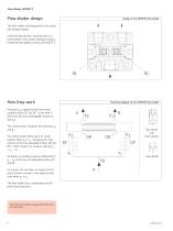
Flow Divider SP/SMT 1 Flow divider design Design of the SP/SMT1 flow divider The flow divider is distinguished by its simple and compact design. Inside the flow divider’s housing there is a control piston, also called a pressure balance. It holds the two nozzles d1 and d2 (DF and DF´). Functional diagram of the SP/SMT1 flow divider Pressure po is applied to the two nonadjustable orifices DF and DF´ at the inlet P. (these are the two exchangeable nozzles d1 and d2). The control piston compares the pressures p1 and p1´. The control piston drifts out of its center position when p1 ≠ p1´....
Open the catalog to page 2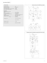
Flow Divider SP/SMT 1 Technical data up to 100 bar 2.5 to 6,5 bar 0 to 100 °C all mineral and synthetic oils 50 to 1300 mm²/s 0.50 l/min 6,00 l/min Mengenteiler A B SP/SMT Teilung Düse Düse P Hydraulics Operating pressure range Input . . . . . . . . . . . . . . . . . . . . . . . . . . . . . . Control pressure loss . . . . . . . . . . . . . . . . Lubricant temperature range . . . . . . . . . . Lubricant . . . . . . . . . . . . . . . . . . . . . . . . . . Operating viscosity . . . . . . . . . . . . . . . . . . Volumetric flow Q0 min. . . . . . . . . . . . . . max. . . . . . . . . . . . . ....
Open the catalog to page 3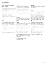
Flow Divider SP/SMT 1 How to select the right flow divider A flow divider splits the supplied flow into two equal individual flows or into two individual flows in a specific ratio. The following specific values must therefore be known to define the right flow divider: • required flow Q1 for lube point 1 • required flow Q2 for lube point 2 • Operating viscosity of the lubricant to be Problem Two lube points should be supplied with oil. The oil flows should be divided as follows: • Lube point 1 with Q1 = 250 cm3/min • Lube point 2 with Q2 = 750 cm3/min. The operating viscosity is 650 mm2/s...
Open the catalog to page 4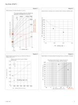
Flow Divider SP/SMT 1 Diagram 1 Determination of nozzle diameters d1 and d2 Diagram 3 Determination of pressure loss corrective factor relative to dividing ratio pressure loss corrective factor in % Volumetric flow cm3/min Example: 1000 cm3/min) The various dividing ratios are achieved by appropiate combinations of d 1 and d 2 Diagram 2 Determination of pressure loss as a function of flow at a dividing ratio of 1:1 pressure loss corrective factor in % pressure loss in bars Decreasing viscosity results in lower pressure loss The pressure loss changes with the viscosity Determination of...
Open the catalog to page 5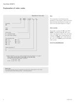
Flow Divider SP/SMT 1 Explanation of order codes Explanation of order codes Assembly SP Type SMT Version key 1 = standard design 2 = with inline strainer Flow dividing ratio 10 = 1:1 20 = 1:2 15 = 1:1.5 25 = 1:2.5 30 = 1:3 35 = 1:3.5 40 = 1:4 Note The composition of the following order example for a flow divider is based on the key data and design specifications on page 4 as well as the associated diagrams on page 5. Order example Flow divider, assembly SP (SP), type SMT1 (SMT1) in standard design (1) with a volumetric ratio between nozzle 1 (d1) and nozzle 2 (d2) of 1:3 (30) with a nozzle...
Open the catalog to page 6
Order No. 1-5017-EN Subject to change without notice! (07/2014) Important product usage information All products from SKF may be used only for their intended purpose as described in this brochure and in any instructions. If operating instructions are supplied with the products, they must be read and followed. Not all lubricants are suitable for use in centralized lubrication systems. SKF does offer an inspection service to test customer supplied lubricant to determine if it can be used in a centralized system. SKF lubrication systems or their components are not approved for use with gases,...
Open the catalog to page 8All SKF Lincoln Automatic Lubrication Systems catalogs and technical brochures
-
 Pump unit PPS30
4 Pages
-
 ECP Product brochure
8 Pages
-
 Product series 143 brochure
24 Pages
-
 Wire rope lubrication system
8 Pages
-
 Single- and Multi-circuit Pumps
16 Pages
-
 LubriLean brochure
4 Pages
-
 1154 flyer
2 Pages
-
 EDL1 product brochure
4 Pages
-
 DSA product brochure
4 Pages
-
 DSC3 product brochure
4 Pages
-
 DSB product brochure
4 Pages
-
 HCC product brochure
2 Pages
-
 LMC 301 product brochure
8 Pages
-
 SFZM product brochure
4 Pages
-
 SP/SMB14 product brochure
8 Pages
-
 SP/SMB13 product brochure
8 Pages
-
 SMBM product brochure
18 Pages
-
 Safeflow product brochure
4 Pages
-
 LP2 / LPC product brochure
8 Pages
-
 PSG product brochure
36 Pages
-
 VP product brochure
20 Pages
-
 VPK product brochure
20 Pages
-
 VPB product brochure
12 Pages
-
 SPVS product brochure
8 Pages
-
 SKF Maxilube Solution
8 Pages
-
 SGA/SG product brochure
6 Pages
-
 SLC product brochure
12 Pages
-
 SL-6 product brochure
4 Pages
-
 SL-32HV product brochure
2 Pages
-
 310 series product brochure
4 Pages
-
 BPH product brochure
4 Pages
-
 Lubrigun product brochure
15 Pages
-
 EOP2 product brochure
2 Pages
-
 MPB product brochure
2 Pages
-
 FK product brochure
12 Pages
-
 VectoLub product brochure
30 Pages
-
 Gear Pump Units brochure
12 Pages
-
 P502 product brochure
2 Pages
-
 LubriLean product brochure
16 Pages
-
 P603S product brochure
8 Pages
-
 P212 product brochure
2 Pages
-
 P205/ P215 product brochure
2 Pages
-
 MKx series product brochure
24 Pages
-
 Product Series OLA, MV and 161
28 Pages
-
 CLK product brochure
8 Pages
-
 Pulse meter IPM
4 Pages
-
 Gear wheel indicator SFZM
4 Pages
-
 Oil conditioning unit OCU
4 Pages
-
 LFC 5000
4 Pages
-
 SSV-D
SSV-D2 Pages
-
 Improved Centro-Matic SL-11
12 Pages
-
 SL-V XL
4 Pages
-
 12-volt Reel 'n F
2 Pages
-
 New 90-lb. Reservoir
12 Pages
-
 HTL 429
4 Pages
-
 Lincoln
8 Pages
-
 AC FlowMaster
12 Pages
-
 EOS
EOS2 Pages
-
 LFR Series
4 Pages
-
 Hand Vacuum Pumps
6 Pages
-
 Pumps PMV Pump Family
16 Pages


