V-Tork Series
1 /2Pages

V-Tork Series
1 /2Pages
Catalog excerpts

V-Tork Series Wiring Diagram VTK-DC N1 Housing Time Delay Guide Time Delay Central LED Power Supply 1 - Power Supply (+) 2 - Power Supply (-) 3 - PNP/NPN Output or +24v/0v (I Máx 500mA) 4 - Ground VTK-DC with M12 connector 1 - Power Supply (+) 2 - Power Supply (-) 3 - PNP/NPN Output or +24v/0v (I Máx 500mA) 4 - Ground VTK-R Universal Power Supply N1 Housing Central LED Time Delay Guide Time Delay Power Supply 1 - Power Supply (+) ( ) 2 - Power Supply (-) ( ) 3 - Ground 4 - NO Contact 5 - Common 6 - NC Contact VTK-R with M12 connector Time Delay Guide 1 - Power Supply (+) ( ) 2 - Power Supply (-) ( ) 3 - NO Contact 4 - Common 5 - NC Contact The different key positions indicate the time delay in seconds.
Open the catalog to page 1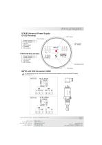
Wiring Diagram VTK-R Universal Power Supply G1/G2 Housing Power Supply 1 - Power Supply (+) ( ) 2 - Power Supply (-) ( ) 3 - Ground 4 - NO Contact 5 - Common 6 - NC Contact VTK-R with M12 connector 1 - Power Supply (+) ( ) 2 - Power Supply (-) ( ) 3 - NO Contact 4 - Common 5 - NC Contact Time Delay Guide Time Delay MVTK with DIN Connector 43650 ! To avoid burning the unit, make sure that the load has been installed in series with the MVTK before powering it up. www.sitron.com - email: [email protected] Sitron - Brasil R. Baronesa de Itu, 83 São Paulo - SP - 01231-001 T.: (5511) 3825-2111 F.: (5511)...
Open the catalog to page 2All Sitron catalogs and technical brochures
 VDX500
6 Pages
 CF12Flow Switch for Low Flow
4 Pages
 CF12EX Proof Flow Switch
4 Pages
 Local Indicator
4 Pages
 Series: SP
27 Pages
 Series: STD
7 Pages
 Series: SPD900
13 Pages
 Series: LH
19 Pages
 Sitron 2016 Line Card
28 Pages
 SV42 V ibration Sensor
3 Pages
 MV42 V ibration Sensor
3 Pages
 SC750 Series
2 Pages
 SC400 - N1 Housing
2 Pages
 CF420
CF4203 Pages
 CN1 & CN2
2 Pages
 wiring duagram
3 Pages


Archived catalogs
 Flow
Flow9 Pages


- Liebherr temperature sensor
- Resistance temperature sensor
- Pressure transmitter
- Liebherr level switch
- Analog pressure transmitter
- Liebherr liquid level switch
- Waterproof pressure transmitter
- Membrane pressure transmitter
- Stainless steel pressure transmitter
- Relative pressure transmitter
- Waterproof temperature sensor
- Pt100 temperature transducer
- Digital pressure transmitter
- Stainless steel temperature transducer
- Liebherr stainless steel level switch
- Level transmitter
- Gas pressure transmitter
- Liquid level transmitter
- Liquid pressure transmitter
- Threaded pressure transmitter