Series: SP
1 /27Pages

Series: SP
1 /27Pages
Catalog excerpts

USER MANUAL Installation, Operation and Maintenance Manual Series: SP Pressure Transmitters
Open the catalog to page 1
Contents Introduction . . . . . . . . . . . . . . . . . . . . . . . . . . . . . . . . . . . . . . . . . . . . . . . . . 3 Models & Dimension . . . . . . . . . . . . . . . . . . . . . . . . . . . . . . . . . . . . . . . . . . 4 Electrical Connection. . . . . . . . . . . . . . . . . . . . . . . . . . . . . . . . . . . . . . . . . . 7 Mounting Notes . . . . . . . . . . . . . . . . . . . . . . . . . . . . . . . . . . . . . . . . . . . . . 10 Installation . . . . . . . . . . . . . . . . . . . . . . . . . . . . . . . . . . . . . . . . . . . . . . . . . 11 Calibration . . . . . . . . . . . . . . . ....
Open the catalog to page 2
Introduction SP Series Pressure Transmitter The SP Series of pressure transmitters are designed to measure the level or pressure of various industrial processes. Models can be mounted with various threaded or flanged process connections. All models are available with 4..20mA (2 wire) output (or voltage outputs). The SP/FA line coms with an integrated Zero and Span adjustment. All units offer excellent stability, repeatibility, accuracy and temperature compensation. HART communications protocol is also available for many models. Each model in this series is offered in pressure ranges that are...
Open the catalog to page 3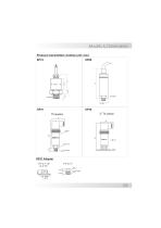
Models & Dimensions Pressure transmitters models (unit: mm) SP68
Open the catalog to page 4
SP98FA with Housing Threaded SP96FA with Housing Threaded Process Connections Threaded Connections
Open the catalog to page 6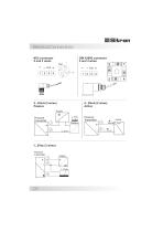
Electrical Connections M12 connector 2 and 3 wires
Open the catalog to page 7
Pressure transmitter Pressure transmitter Pressure transmitter HART Modem connection Transmitter Power Supply Padrão Hart® mode
Open the catalog to page 8
Zero & Span adjustment
Open the catalog to page 9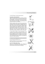
Mounting Notes 1) Use PTFE tape or o'rings to seal the system. Transmitters with cable gland: Tighten the cable gland as much as possible so that the cable is securely in place and cannot be pulled through the cable gland. This will help insure that no moisture is able to infiltrate into the housing. Don´t forget to attach the housing cover and tighten all three screws into position so that there is no infiltration. 2) Before installing, make sure the cable connections are correct and that the line voltage is compatible with the specifications of the equipment. Use reliable cables and make sure...
Open the catalog to page 10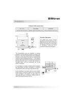
Installation Pressure of the Liquid Column Water Column System MKgfs Density Specific Gravity Principle of Operations The weight of the column of liquid generates hydrostatic pressure on the diaphragm of the sensor. When the density of the product is constant and the quantity of the liquid is increased or decreases, there will be a proportional output from the sensor . The transmitters can be installed in various positions, but the following needs to be taken into account: For level measurement the installation should be at the base of the tank or at the point of minimum level measurement (fig.1)....
Open the catalog to page 11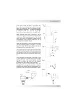
Installation In situations where the tank is suspended, the transmitter should always be installed in a point below the connection using the sealing system with capillary connection. This type of installation is required when you want to mount the transmitter in a better position for viewing (Fig. 3) . Sealing Cappilary Note: Evaluate what type of product is to be measured. Aggressive products can damage the membrane of the sensor element or of the o´ring seal. That is why it is necessary to determine the compatability of the product before the unit is purchased and installed. (Fig. 4). Install...
Open the catalog to page 12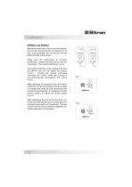
Calibration SP98FA and SP96FA Before the calibration of the unit is first tested, the process should be free of pressure or (if that is not possible) the unit should first be tested outside of the vessel. Make sure the muliti-meter is correctly connected in series with the source and the instrument. The scale should be set to mA First confirm that the current output is at 4mA (for SPFA units you can adjust the trimpot "zero".) Turning the trimpot clockwise increases the current value, and turning it counterclockwise decreases the value (Fig.1). After adjusting (if necessary) the 4mA (zero) install...
Open the catalog to page 13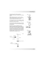
Handling Seal the thread with Teflon tape before installation. Do not turn or handle by the housing (Fig. 1). When tightening the sensor, use only use the 316S.S. hexagon fitting to achieve a seal, do not twist with the body of the sensor. (Fig. 2). The transmitter should not be dropped or suffer any impact or fall, as this can damage the electronics or the sensor (Fig.3). Do not insert any object into the entry point of the transmitter supply. This will immediately damage the membrane. Electrical connection with DIN connector: Figure 4. Shows the steps for proper assembly of the connector. When...
Open the catalog to page 14
Technical Specifications@ Red (+) @ Black (-) @ Yellow (Out) 3 wires Application
Open the catalog to page 17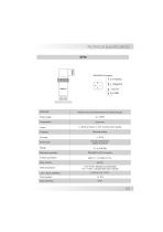
DIN 43650 Connector (+) Positivo (-) Negativo Out (V) ( I ) GND
Open the catalog to page 18
Sitron Technical Specifications SP10 crzj 0 Red (+) 0 Green (-) 0) Yellow (Out) 3 wires
Open the catalog to page 19
DIN 43650 connector e—X E (+) Positive
Open the catalog to page 20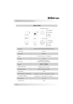
DIN 43650 connector (+) Positive (-) Negative Out (V) ( I )GND M12 connector (+) Positive (-) Negative Out (V) ( I )GND
Open the catalog to page 21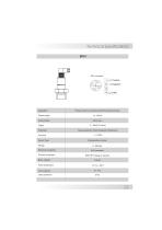
M12 connector (+) Positive (-) Negative( I )GND Application
Open the catalog to page 22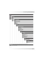
BSP FLANGE ANSI 150# 316 SS FLANGE ANSI 150# PVC FLANGE ANSI 150# 346 SS NPT SMS Female SMS Macho TRI-CLAMP DIN - Female 316 SS HOUSING SC None N1 Small Nylon ELECTRICAL CONNECTION 1 2 7 D L Y M 1/2" BSP PC 1/2" BSP PC 1/2” NPT DIN Connector 43650 Cable length (especify) M16 metal w/ 2m Cable M12 Connector RANGE R Especify SENSOR TYPE 0 A B C CP D G H X None 316 SS Silicon (Absolute) 316 SS (Olive oil) Ceramic PVC Body Ceramic sensor 316 SS Differencial silicon 316 SS Gauge silicon 316 SS Gauge Olive oil Others OPTION F Flush mounted membrane P PVC body and connection PE Polypropylene Body and...
Open the catalog to page 24
Terms & Conditions Sitron's TERMS & CONDITIONS Design: Sitron reserves the right to make any alterations or changes necessary to improve the Products, correct defects or to make the Products safer, without prior notice or consent by Buyer. Pricing: All stipulated amounts shall be in US dollars and all prices quoted are valid for thirty (30) days from date of offer, unless otherwise stated. Safety and Instructions: The Buyer ensures that it and all its representatives and agents will observe all safety and technical instructions in Sitron's operating manuals, catalogs or other directions or instructions...
Open the catalog to page 25All Sitron catalogs and technical brochures
 VDX500
6 Pages
 CF12Flow Switch for Low Flow
4 Pages
 CF12EX Proof Flow Switch
4 Pages
 Local Indicator
4 Pages
 Series: STD
7 Pages
 Series: SPD900
13 Pages
 Series: LH
19 Pages
 Sitron 2016 Line Card
28 Pages
 SV42 V ibration Sensor
3 Pages
 MV42 V ibration Sensor
3 Pages
 SC750 Series
2 Pages
 SC400 - N1 Housing
2 Pages
 CF420
CF4203 Pages
 CN1 & CN2
2 Pages
 V-Tork Series
2 Pages
 wiring duagram
3 Pages


Archived catalogs
 Flow
Flow9 Pages


- Liebherr temperature sensor
- Resistance temperature sensor
- Liebherr level switch
- Analog pressure transmitter
- Liebherr liquid level switch
- Waterproof pressure transmitter
- Membrane pressure transmitter
- Stainless steel pressure transmitter
- Relative pressure transmitter
- Waterproof temperature sensor
- Pt100 temperature transducer
- Digital pressure transmitter
- Stainless steel temperature transducer
- Liebherr stainless steel level switch
- Level transmitter
- Gas pressure transmitter
- Liquid level transmitter
- Liquid pressure transmitter
- Threaded pressure transmitter