Z10 - Auto Bleeder
1 /3Pages

Z10 - Auto Bleeder
1 /3Pages
Catalog excerpts

Purpose Even though every hydraulic specialist knows that each installation is to be bled carefully after final assembly, over and over again seal damages occur which can be identified as a result of combustion processes within the pressure chamber (Diesel effect). On lip seals, you can see those damages as cracks in the seals along the bottom of the seal groove (Fig. 4), which start at the groove, making their way all the way through to the back of the seal. On seals damaged in such a way, you can regularly notice a burnt smell, sometimes you can also see burn marks on the crack edges. The metal shaft surface is also often damaged (Fig. 4). You can find scratches in the direction of movement (expansion channels) or impact holes (similar to cavitation). Other devices, like hydraulic cylinders, are more or less flushed through in each cycle. The remaining air is carried back to the tank where it can be exhausted. In a clamping head, every activation often means that the oil/ air column is pushed a little back and forth only in the line. As a result, air inclusions will not be removed, they rather collect at higher positioned places in the form of foam, possibly also within the pressure chamber of the Clamping head. Depending on the rate of the pressure rise etc. it may come to an ignition point due to compression. A steep pressure drop is also dangerous, when gas (previously diffused into the seal material under high pressure) is expanded very fast. In this case, the seal material can be damaged from the inside. The usual one-time manual bleeding of the system is not always enough, especially when the supply line to the Clamping head is vertical and air enrichment occurs. In this case, an autobleeder is recommended. When properly applied the main cause for early seal failure can be fought effectively. Function The function of the auto-bleeder is based on the difference of viscosity of oil and air. A piston located in the bore of the housing with defined radial clearance, works with pressure increases and decreases. The piston will open the inlet with increases in the pressure during start-up from zero to over approx. 2 bar. Accumulated air moves out through the clearance around the piston while following fluid, with its higher flow resistance, will close the outlet by instantly pushing up the piston. The outlet stays closed, until during pressure decrease, the pressure falls below about 2 bar, then the piston moves down. During the transition, fluid is leaking out. The higher the gas concentration, the slower the pressure decrease will take place. Thereby, remaining oil-air-foam will be removed from the system. A discharge air, foam, leakage oil The auto-bleeder cannot work if the pressure does not drop below approx. 2 bar again. In case of negative pressure within the hydraulic system, the auto-bleeder works like a check valve. Therefore, drawing in air is impossible. SITEMA GmbH & Co. KG . G.-Braun-StraGe 13 . D-76187 Karlsruhe . Phone: +49(0)721/98661-0 . Fax: -11 . www.sitema.com
Open the catalog to page 1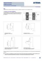
Technical Information SITEMA auto-bleeder For the prevention of seal damages TI-Z10-EN-02/2015 Use SITEMA offers two different alternatives, either as a separate component or as an integrated version. 1 Separate auto-bleeder EM MEA-4 G1/4 direction of flow The auto-bleeder is to be installed vertically and above the clamping head with the direction of flow pointing upwards. The pictures show the recommended installation (recommendation: a > 200 mm). Clamping head vertical, auto-bleeder at T-piece above port L. clamping head clamping head Clamping head vertical, auto-bleeder at T-piece above port...
Open the catalog to page 2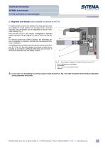
2 Integrated auto-bleeder (only available for series K and K/TA) For Safety Catchers that have sufficient housing wall thickness, are installed in a fixed position (not moving) and are mounted vertically, the auto-bleeder can be integrated as shown in principle drawing Fig. 4. From the end of 2011, this version is integrated in standard Safety Catchers K 90 and bigger, as well as K/TA 100 and bigger. For special construction Safety Catchers, the integrated version is available on demand, provided the housing wall thickness is sufficient. A suitable pipe line provided by the customer has to be...
Open the catalog to page 3All SITEMA catalogs and technical brochures
 electric Safety Brake linear
2 Pages
 PowerStroke SITEMA
9 Pages
 SITEMA_Flyer_2020
2 Pages
 TI-S10 Safety Locks
4 Pages
 TI-A10
7 Pages
 TI-P30
1 Page
 SITEMA Applications
2 Pages
 Dimensions, type KRG
1 Page
 Dimensions, type KRP/T
1 Page
 Dimensions, type KRP
1 Page
 Dimensions, type KR, K
2 Pages
 SITEMA Safety Catchers
2 Pages
 SITEMA Locking Units KFH
6 Pages
 STB10 Rod Attachment STB
3 Pages
 F60 Dimensions, type KFHA
6 Pages
 SITEMA Safety Locks KRG
1 Page
 SITEMA company
15 Pages
 Locking Units KFPC
3 Pages
 Locking units series KFPA
4 Pages


- Double-acting cylinder
- SARRALLE lift table
- Hydraulic cylinder
- SARRALLE scissor lift table
- SARRALLE pneumatic cylinder
- SARRALLE stationary lift table
- SARRALLE friction brake
- SARRALLE hydraulic lift table
- Industrial cylinder
- Standard cylinder
- ISO cylinder
- SARRALLE electromagnetic brake
- Industrial control system
- Cylinder with piston rod
- SARRALLE heavy load lift table
- SARRALLE hydraulic clamping
- Safety brake
- Monitoring control system