TI-S10 Safety Locks
1 /4Pages

TI-S10 Safety Locks
1 /4Pages
Catalog excerpts

Technical Information TI-S10 Safety Locks 0 high holding force by self-reinforcing clamping 0 hydraulic or pneumatic actuation 0 for static loads For further information on technical data please see: • “Technical Data Sheet TI-S11” (hydraulic pressure version: series KRG) • “Technical Data Sheet TI-S12” (pneumatic pressure version: series KRGP) A detailed description of control, mounting and performance test of the SITEMA Safety Locks can be found in: • “Operating Manual BA-S11” (hydraulic version) • “Operating Manual BA-S12” (pneumatic version) 2.1 Clamping released The clamping system consists of a conical clamping sleeve (3) movable within the conical housing (2). In released condition, the annular piston (4) is pressurized (p) and keeps the clamping sleeve pushed against the set of disc springs (1). The rod (5) can move freely in both directions. 2.2 Secure the load The Safety Lock secures the load as soon as pressure is released from the annular piston (4). Then, the disc springs (1) push the clamping sleeve (3) into the cone of the housing, whereby an initial friction contact between rod and clamping sleeve is achieved (contact condition). At this point, the Safety Lock secures the load but has not yet taken the load. 2.3 Take the load The holding force, however, is not built up until the rod has been moved by the load. Due to the self-reinforcing static friction at the rod, the clamping systems contracts. During this process, the movement of the rod is very small. Even at larger sizes the movement does not exceed 2 mm when the admissible load M is applied (see tapering distance e in Fig. 1).
Open the catalog to page 1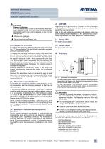
J TION Danger of damage The rod does not slip if there is an overload (see force / path diagram in Fig. 1). Loads that exceed twice the admissible load M can lead to damage on the rod and Safety Lock. K Choose the right type. K Do not overload the Safety Lock. 2.4 Release the clamping To release the clamping after securing the load (see Chapter 2.2 “Secure the load”), it is sufficient to apply the operating pressure to pressure port L. To release the clamping after taking up the load (see Chapter 2.3 “Take the load”), the rod must additionally be moved back in opposite direction to the load direction...
Open the catalog to page 2
4.1 Pressure fluids Safety Locks mostly are hydraulically actuated. For smaller sizes, also pneumatic versions are available. For hydraulic series KRG: Hydraulic oil (HLP) in accordance with DIN 51524-2:2006 must be used as pressure fluid. Please consult SITEMA before using any other fluids. For pneumatic series KRGP: The compressed air must be dried and filtered. SITEMA recommends compressed air according to ISO 8573-1:2010 [7:4:4]. 4.2 Actuation using 3/2-way valve In most applications an actuation as suggested in Fig. 2 is used. During every operational cycle, the 3/2-way valve is actuated...
Open the catalog to page 3
Technical Information SITEMA Safety Locks Hydraulic or pneumatic actuation TI-S10-EN-09/2015 8 Required risk assessment 12.1 Stationary Safety Lock It must be ensured that the dimensions and arrangement of a Safety Lock used in safety-relevant applications meet the requirements of the risk evaluation EN ISO 12100:2010 and also comply with any further standards and regulations applicable for the intended use. The Safety Lock alone principally cannot form a complete safety solution. It is however suitable to be part of such a solution. Furthermore, all attachments and fixations have to be dimensioned...
Open the catalog to page 4All SITEMA catalogs and technical brochures
 electric Safety Brake linear
2 Pages
 PowerStroke SITEMA
9 Pages
 SITEMA_Flyer_2020
2 Pages
 TI-A10
7 Pages
 TI-P30
1 Page
 SITEMA Applications
2 Pages
 Dimensions, type KRG
1 Page
 Dimensions, type KRP/T
1 Page
 Dimensions, type KRP
1 Page
 Dimensions, type KR, K
2 Pages
 SITEMA Safety Catchers
2 Pages
 SITEMA Locking Units KFH
6 Pages
 STB10 Rod Attachment STB
3 Pages
 F60 Dimensions, type KFHA
6 Pages
 Z10 - Auto Bleeder
3 Pages
 SITEMA Safety Locks KRG
1 Page
 SITEMA company
15 Pages
 Locking Units KFPC
3 Pages
 Locking units series KFPA
4 Pages


- SARRALLE cylinder
- Double-acting cylinder
- SARRALLE lift table
- Hydraulic cylinder
- SARRALLE scissor lift table
- SARRALLE pneumatic cylinder
- SARRALLE stationary lift table
- SARRALLE friction brake
- SARRALLE hydraulic lift table
- Industrial cylinder
- Standard cylinder
- ISO cylinder
- SARRALLE electromagnetic brake
- Industrial control system
- Cylinder with piston rod
- SARRALLE heavy load lift table
- SARRALLE hydraulic clamping
- Safety brake
- Monitoring control system