TI-M10 Mechanical Valve Actuator MVA
1 /3Pages

TI-M10 Mechanical Valve Actuator MVA
1 /3Pages
Catalog excerpts
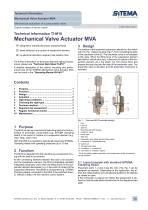
SiTEMA ■ Expertise in Safety Technical Information Mechanical Valve Actuator MVA Mechanical actuation of a pneumatic valve English translation of German original Technical Information TI-M10 Mechanical Valve Actuator MVA 0 designed to actuate pneumatic clamping heads 0 direct detection of a rupture of suspension element 0 no electrical activation required, fast reaction time For further information on technical data and optional accessories, please see “Technical Data Sheet TI-M11”. A detailed description of the control, mounting and performance test of the SITEMA Mechanical Valve Actuator MVA can be found in the “Operating Manual BA-M11”. 1 Purpose The MVA serves as a mechanical switching device for fast activation of pneumatic components (e.g. SITEMA Clamping Head) in the event of rupture of a suspension element (e.g. rope, strap, chain, etc.). With the MVA it is possible to operate all pneumatic SITEMA-Clamping Heads with operating pressures up to 10 bar. 2 Function The MVA is integrated into the machine as a component moving with the load to be secured. As the connecting element between the load to be secured and the suspension element, the MVA immediately actuates integrated pneumatic valve when the lifting force on the suspension element decreases (e.g. in the event of rupture of the suspension element). This allows a component (e.g. SITEMA Clamping Head) connected to the MVA to be switched directly, without a detour via the machine control system. 3 Design The traction of the tensioned suspension element on the switch rod (10), Fig. 1 keeps the stop ring (7), from contacting the slide of the pneumatic valve (8). The pneumatic valve is not actuated in this state. When the lifting force of the suspension element falls below a critical value (e.g. in the event of rupture of the suspension element, etc.), the switch rod (10) moves down and presses the stop ring onto the slide of the pneumatic valve. The pneumatic valve is actuated, and the pneumatic component is activated. Fig. 1: Overview MVA (example design) 1 Fork 2 Locknut 3 Stop nut 4 Mounting side with threads 5 Holder for valve 6 Name plate 7 Stop ring 8 Pneumatic valve (slide operated slide valve) 9 Connection 2: “release pressure” 10 Switch rod 11 Through bore-holes 12 Connection 1: “exhaust air” 13 Connection 3: “pressure supply” * For a non-safety-related application, the configuration of the connections can be modified. 3.1 Layout (sample with standard SITEMA Clamping Head) Pneumatic ports 1,2 and 3 see (9), (12), (13), Fig. 1 can be assigned as required. Depending on the application, this allows the initial position (not actuated/actuated) to be defined as closed or open. If the connection is relevant to safety, the assignment is defined so that the safe state corresponds to the depressurized state. SITEMA GmbH & Co. KG . G.-Braun-Stral3e 13 . D-76187 Karlsruhe . Phone: +49(0)721/98661-0 . Fax: -11 . www.sitema.com
Open the catalog to page 1
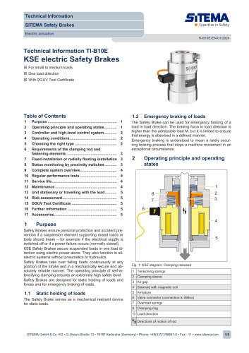
1 Suspension element (e.g. rope, strap, chain, etc.) 2 MVA 3 SITEMA Clamping Head, pressure version (e.g. KSP, KRP, KFP etc.) 4 Load to be secured J NING! Danger if incorrectly incorporated into the lifting drive! If, in the event of an emergency, the lilting force does not fall below the triggering force, the MVA will not actuate the pneumatic valve, which can lead to a dangerous situation. Error example 1: The drive shaft breaks, but the rope is still held under residual tension by the gear lock while the load moves downwards. Error example 2: On a deflection pulley, the suspension element...
Open the catalog to page 2
5 Operating conditions The immediate environment of the MVA must be dry and clean. The machine manufacturer must take measures to prevent contamination. In case of doubt, please contact SITEMA. The permitted surface temperature is 0 to +60 °C. For protection against corrosion the MVA is zinc-nickel coated. 6 Choosing the right type The data tables in “Technical Data Sheet TI-M11” show the admissible load (M) of the various types. The static load acting on the MVA must not exceed the admissible load (M) in any operating state. The acceleration of the load must not exceed 5 m/s2. 7 Pressure medium The...
Open the catalog to page 3All SITEMA catalogs and technical brochures
 electric Safety Brake linear
2 Pages
 PowerStroke SITEMA
9 Pages
 SITEMA_Flyer_2020
2 Pages
 TI-S10 Safety Locks
4 Pages
 TI-A10
7 Pages
 TI-P30
1 Page
 SITEMA Applications
2 Pages
 Dimensions, type KRG
1 Page
 Dimensions, type KRP/T
1 Page
 Dimensions, type KRP
1 Page
 Dimensions, type KR, K
2 Pages
 SITEMA Safety Catchers
2 Pages
 SITEMA Locking Units KFH
6 Pages
 STB10 Rod Attachment STB
3 Pages
 F60 Dimensions, type KFHA
6 Pages
 Z10 - Auto Bleeder
3 Pages
 SITEMA Safety Locks KRG
1 Page
 SITEMA company
15 Pages
 Locking Units KFPC
3 Pages
 Locking units series KFPA
4 Pages


- SARRALLE cylinder
- Double-acting cylinder
- SARRALLE lift table
- Hydraulic cylinder
- SARRALLE scissor lift table
- SARRALLE pneumatic cylinder
- SARRALLE stationary lift table
- SARRALLE friction brake
- SARRALLE hydraulic lift table
- Industrial cylinder
- Standard cylinder
- ISO cylinder
- SARRALLE electromagnetic brake
- Industrial control system
- Cylinder with piston rod
- SARRALLE heavy load lift table
- SARRALLE hydraulic clamping
- Safety brake
- Monitoring control system