SITEMA Safety Catchers hydraulic / for compressive load

SITEMA Safety Catchers hydraulic / for compressive load
- Admissible Force (M): The force exerted by the mass on the clamping device. The holding force ranges from 2x to 3.5x M.
- Operating Pressure: Minimum pressure is 40 bar, with a spring base requiring 60 bar for release without lifting. Maximum working pressure is 250 bar.
- Hydraulic Volume: Specific volumes are provided for each model.
- Port LL: Used for air-bleeding, recommended to install an Auto-Bleeder.
- Port T: Used for pressure compensation, equipped with an air filter. A hose is recommended if moisture or aggressive media are present.
- Proximity Switches: Holders for standard M12x1 switches with a 2 mm nominal distance, except for KR 25 and KR 28 which use M8x1 switches.
- Ensure proper alignment of ports to avoid misalignment up to +/-4°.
- Connect the automatic air-bleeder to the tank to manage oil-air mix escape.
Catalog excerpts

Technical Data Sheet SITEMA - Safety Catcher K and KR Hydraulic actuation / Compressive load TI-A11-EN-01/2011 English translation of German original Technical Data Sheet TI-A11 Safety Catcher KR Load direction compressive (to mounting surface) General information, particularly regarding purpose, function, choosing right type and control is provided in "Technical Information TI-A10“. Furthermore important practical advices are given in the "Operating Manual BA-A11“. 4 x G2 T2 Load direction ø D 1 - 0 ,, 2 -0 4 øZe8 G1 LL øL2 øD ødf7/h6 X-0,2 ° x60 L1 L T1 G1/4 T 6 1 3x20° 2 G1/4 = max.30 w Due to tolerances the ports 1 and 2 may be misaligned up to +/-4° relative to port L. Port: release pressure see 2 Alternativ port: release pressure see 3 Port: pressure compensation see 6 Proximity switch port:1 Signal „Load secured“ see 5 Proximity switch port:2 Signal „unclamped“ see 5 Y-0,2 HL ø26 H1 H2 H Fig. 1: Dimensions Safety Catcher KR (CAD-Files download at www.sitema.com) Type Ident.-No. 1 d M 4 D D1 H Y Z X L1 G1 T1 L2 G2 T2 V HL 3 H1 H2 w Weight kg mm kN mm mm mm mm mm mm mm mm mm mm mm KR 25 KR 025 30 25 10 71 81 152 5 40 3 56 M6 15 64 M5 12 3 48 84 130 0° 4 KR 28 KR 028 30 28 15 82 92 169 5 45 3 65 M8 15 73 M5 12 4 50 88 145 0° 6 KR 36 KR 036 30 36 33 106 123 211 8 52 3 80 M8 25 56 M6 12 5 62 141 125 50° 13 KR 40 KR 040 30 40 33 106 123 211 8 52 3 80 M8 20 56 M6 12 5 62 141 125 50° 13 KR 45 KR 045 30 45 40 120 137 230 8 60 3 100 M10 25 66 M6 10 9 64 114 154 0° 18 24 mm mm mm cm KR 50 KR 050 30 50 52 125 142 264 8 65 3 110 M10 25 66 M6 12 10 64 119 160 0° KR 56 KR 056 30 56 67 140 156 262 8 70 3 115 M10 25 75 M6 12 11 72 122 166 0° 24 KR 63 KR 063 30 63 100 160 177 285 10 80 5 140 M10 25 85 M6 13 12 66 125 164 0° 38 KR 70 KR 070 30 70 107 172 188 302 10 90 3 140 M10 25 100 M8 16 15 73 129,5 166 0° 45 KR 80 KR 080 30 80 133 194 212 322 10 100 3 160 M10 25 110 M8 16 16 72 0° 62 bold types = recommended standard, on stock 1 M is the admissible force the mass to be secured exerts on the clamping device. The holding (braking) force for dry running or mineraloil wetted shafts is not less than 2 x M, but will not exceed 3,5 x M. 2 Minimum operating pressure is 40 bar. In case a spring base is installed, for releasing without lifting the required pressure is 60 bar, conf. "Technical Information TI-A20“. Admissible working pressure is 250 bar. 3 As supplied port LL is plugged by a plug screw. It may be used alternatively to port L and is usefull for air-bleeding. It is generally recommended to install the Auto-Bleeder as descibed in the "Technical Information TI-Z10“ at port LL (or L respectively). 128 176 Subject to modification without prior notice 4 Hydraulic operating volume. 5 Proximity switch holders are provided for standard proximity switches M12x1 shielded and with a nominal switching distance of 2 mm, except KR 25 and KR 28: M8x1 with nominal distance 1,5 mm. For easier service, the proximity switch holders have a positive stop and are presetted when deliverd from the factory. 6 Port T is used for pressure compensation (breathing). It is plugged with an air filter element. If, however, moisture or aggressive media are present, a hose instead of the filter must be installed to connect the device with a clean atmosphere (e.g. hydraulic tank). SITEMA GmbH & Co.KG . Im Mittelfeld 10 . D-76135 Karlsruhe . Phone: +49(0)721/98661-0 . Fax: -11 . www.sitema.com 1/2
Open the catalog to page 1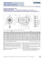
Technical Data Sheet SITEMA - Safety Catcher K and KR Hydraulic actuation / Compressive load TI-A11-EN-01/2011 Technical Data Sheet TI-A11 Safety Catcher K Load direction compressive (to mounting surface) General information, particularly regarding purpose, function, choosing right type and control is provided in "Technical Information TI-A10“. Furthermore important practical advices are given in the "Operating Manual BA-A11“. 4 x G2 Alternativ port: release pressure see 3 Port: pressure compensation see 6 1 Proximity switch port:1 Signal „Load secured“ see 5 2 Proximity switch port:2 Signal...
Open the catalog to page 2All SITEMA catalogs and technical brochures
 electric Safety Brake linear
2 Pages
 PowerStroke SITEMA
9 Pages
 SITEMA_Flyer_2020
2 Pages
 TI-S10 Safety Locks
4 Pages
 TI-A10
7 Pages
 TI-P30
1 Page
 SITEMA Applications
2 Pages
 Dimensions, type KRG
1 Page
 Dimensions, type KRP/T
1 Page
 Dimensions, type KRP
1 Page
 Dimensions, type KR, K
2 Pages
 SITEMA Safety Catchers
2 Pages
 SITEMA Locking Units KFH
6 Pages
 STB10 Rod Attachment STB
3 Pages
 F60 Dimensions, type KFHA
6 Pages
 Z10 - Auto Bleeder
3 Pages
 SITEMA Safety Locks KRG
1 Page
 SITEMA company
15 Pages
 Locking Units KFPC
3 Pages
 Locking units series KFPA
4 Pages


- SARRALLE cylinder
- Double-acting cylinder
- SARRALLE lift table
- Hydraulic cylinder
- SARRALLE scissor lift table
- SARRALLE pneumatic cylinder
- SARRALLE stationary lift table
- SARRALLE friction brake
- SARRALLE hydraulic lift table
- Industrial cylinder
- Standard cylinder
- ISO cylinder
- SARRALLE electromagnetic brake
- Industrial control system
- Cylinder with piston rod
- SARRALLE heavy load lift table
- SARRALLE hydraulic clamping
- Monitoring control system
- Safety brake