P11 - Dimensions type FSK (hydraulic)
1 /8Pages

P11 - Dimensions type FSK (hydraulic)
1 /8Pages
Catalog excerpts

Technical Information SITEMA PowerStroke FSK Locking, actuating and releasing by hydraulic pressure TI-P11-EN-01/2019 SITEMA PowerStroke Mold closing devices series FSK drive system for powerful forces on a short stroke hydraulic actuation closing force up to 180 tonnes option FSK-SVE: For rods that move in and out 1 Function The mold closing device PowerStroke series FSK clamps and actuates a rod in one direction (closing direction). A force proportional to the operating pressure is exerted to the rod by friction. A detailed description regarding control and use of the PowerStroke FSK is given in the “Assembly Instructions MAP11”. Application example: Schematic diagram of mold press with 4 x SITEMA PowerStroke FSK Application example: Option for rods that move in and out with 4 x SITEMA PowerStroke FSK-SVE 2 Applications The PowerStroke FSK with its integrated short stroke cylinder is typically used in: • blow molding to close and press the mold • injection die molding to close and generate the closing force • other applications requiring powerful forces on a short stroke 3 FSK and FSK-SVE In addition to the standard design FSK, the FSK-SVE option is also available (SVE is a combination of German words meaning “rod exits the unit”). With the FSK-SVE option, the rod is permitted to move in and out between the opening and closing strokes. The FSK-SVE option has a hardened centering ring that centers the rod in relation to the clamping system. The rod openings in the standard design FSK are equipped with guiding strips and wipers. SITEMA GmbH & Co. KG . G.-Braun-Straße 13 . D-76187 Karlsruhe . Phone: +49(0)721/98661-0 . Fax: -11 .
Open the catalog to page 1
PowerStroke FSK on the moving machine element 1. Clamping is released, PowerStroke FSK can be moved in closing direction 4 Function description The following function description refers to a case where the PowerStroke FSK is mounted on the moving machine element. The rod acts as a connection to the stationary machine element. The closing direction is shown as it would appear in this case. Alternatively, the PowerStroke FSK can also be mounted on the stationary machine element. In this case, the rod is moving and the closing direction is reversed. The clamping system consists of the clamping sleeve...
Open the catalog to page 2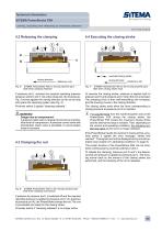
Technical Information SITEMA PowerStroke FSK Locking, actuating and releasing by hydraulic pressure TI-P11-EN-01/2019 4.4 Executing the closing stroke executed closing stroke closing direction Fig. 5: closing direction SITEMA PowerStroke FSK on moving machine part; state when clamping released SITEMA PowerStroke FSK on the moving machine part; state when closing stroke ends If pressure port L receives the required operating pressure (pressure ports K and V not under pressure), the housing (a), Fig. 5 moves against the closing direction as far as the stop and opens the clamping system (see Fig....
Open the catalog to page 3
5.1 Mounting The PowerStroke FSK is integrated in the system via the mounting side (see “Assembly Instructions MA-P11"). During installation, make sure that no constraint forces occur transverse to the rod. Often, this cannot be guaranteed through exact alignment or high-precision machining alone. J Constraint forces transverse to the rod can create increased material stress and can damage both the PowerStroke FSK and the clamping rod. Vertical installation of the standard design FSK: In order to avoid constraint forces transverse to the rod, either the PowerStroke FSK must be screwed radial...
Open the catalog to page 4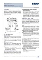
Technical Information SITEMA PowerStroke FSK Locking, actuating and releasing by hydraulic pressure SiTEMA ■ Expertise in Safety 5.4 Actuation Connect the pressure supply to pressure ports L, K and V (alternatively LL, KK and vV). We recommend connecting auto-bleeders (8), Fig. 8 (not in scope of delivery; available as optional extras, see “Technical Information TI-Z10”) to the pressure ports that are not in use (or to the supply pipes of the used pressure ports). Fig. 8: Basic diagram of actuation Pressure control The flow rate and pressure at pressure port L and K can be variably adjusted in...
Open the catalog to page 5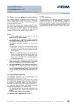
1. In the standard design, the rod must not exit the PowerStroke FSK during operation. 2. The rod may exit the PowerStroke FSK-SVE between the closing strokes. All sizes of the standard design FSK are available as the FSK-SVE option. The following additionally applies to the PowerStroke FSK-SVE: HThe rod may only move into or out of the PowerStroke FSK-SVE on the centering ring side when the clamping system is released (pressure applied, proximity switch 2 active). H Before pre-loading and clamping, the rod must be retracted by at least the minimum insertion depth. The minimum insertion depth...
Open the catalog to page 6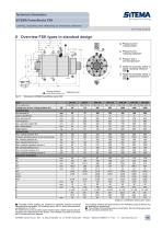
Technical Information SiTEMA ■ Expertise in Safety Locking, actuating and releasing by hydraulic pressure 6 Overview FSK types in standard design © Pressure port K “closing stroke” © Pressure port L “clamping released” © Pressure port V “pre-load pressure” © Holder for proximity switch 2, signal “clamping released” see O © Holder for proximity switch 3, signal “stroke limit reached” see O O Proximity switch holders are provided for standard inductive proximity switches (flush mountable, NO (normally open), M8 x 1 with a nominal switching distance of 1.5 mm). For easier service, the proximity...
Open the catalog to page 7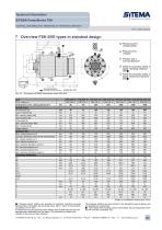
Subject to modification without prior notice O Proximity switch holders are provided for standard inductive proximity switches (flush mountable, NO (normally open), M8 x 1 with a nominal switching distance of 1.5 mm). For easier service, the proximity switch holders have a depth stop and are preadjusted when delivered from the factory. The switches only need to be inserted to the stop and then clamped. © Pressure port K “closing stroke” © Pressure port L “release” ® Pressure port V “pre-load pressure” © Holder for proximity switch 2, signal “clamping released” see O © Holder for proximity switch...
Open the catalog to page 8All SITEMA catalogs and technical brochures
 electric Safety Brake linear
2 Pages
 PowerStroke SITEMA
9 Pages
 SITEMA_Flyer_2020
2 Pages
 TI-S10 Safety Locks
4 Pages
 TI-A10
7 Pages
 TI-P30
1 Page
 SITEMA Applications
2 Pages
 Dimensions, type KRG
1 Page
 Dimensions, type KRP/T
1 Page
 Dimensions, type KRP
1 Page
 Dimensions, type KR, K
2 Pages
 SITEMA Safety Catchers
2 Pages
 SITEMA Locking Units KFH
6 Pages
 STB10 Rod Attachment STB
3 Pages
 F60 Dimensions, type KFHA
6 Pages
 Z10 - Auto Bleeder
3 Pages
 SITEMA Safety Locks KRG
1 Page
 SITEMA company
15 Pages
 Locking Units KFPC
3 Pages
 Locking units series KFPA
4 Pages


- Double-acting cylinder
- SARRALLE lift table
- Hydraulic cylinder
- SARRALLE scissor lift table
- SARRALLE pneumatic cylinder
- SARRALLE stationary lift table
- SARRALLE friction brake
- SARRALLE hydraulic lift table
- Industrial cylinder
- Standard cylinder
- ISO cylinder
- SARRALLE electromagnetic brake
- Industrial control system
- Cylinder with piston rod
- SARRALLE heavy load lift table
- SARRALLE hydraulic clamping
- Safety brake
- Monitoring control system