 Website:
SITEMA
Catalog excerpts

Technical Information TI-KRM-001 Safety Catcher KRM 0 High holding force by self-intensifying clamping 0 mechanical triggering and releasing A detailed description of the control, assembly and operational test of the Safety catchers KRM can be found in the Operating Manual BA-KRM-001“. 1 Purpose Safety Catcher KRM are used where protection of personnel and accident prevention must be achieved in connection with loads or tools lifted by a chain, belt, rope etc. in case of rupture of a lifting menber. Safety Catcher KRM catch falling masses infinitely variable at any position of the stroke, in a mechanically secure and absolutely reliable manner. The design principle of the self-intensifying clamping ensures an extremely high safety level. The Safety Catcher KRM is mechanically kept released by the lifting force of the chain etc. and engages immediately in case of breakdown of the force. Afterwards the energy of the falling massses is used to intensify the clamping action in an ingenious manor. SITEMA GmbH & Co. KG . G.-Braun-StraUe 13 . D-76187 Karlsruhe . Phone: +49(0)721/98661-0 . Fax: -11 . www.sitema.com
Open the catalog to page 1
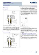
Technical Information SITEMA - Safety Catcher KRM Mechanical actuation TI-KRM-001-EN-04/2008 Lifting force The Safety Catcher KRM becomes effective as soon as the lifting force drops below a critical limit due to any failure. The action of the springs then causes the clamping jaws (3) Fig. 3 to clamp the shaft (1) Fig. 3 firmly, thus securing the load. The full clamping force is built up by as the Safety Catcher KRM together with the falling load is moving along the shaft. Due to the self-intensifying static friction at the shaft, the clamping jaws (3) Fig. 3 are drawn into the clamping...
Open the catalog to page 2
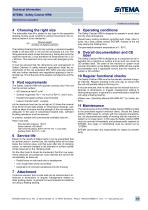
4 Choosing the right size The admissible load M is stated for any type in the respective drawing. During usual conditions (vertical movement), the criteria as below is to be maintained.. _Moved weight Number of Safety Catchers The holding (braking) force for dry running or mineral-oil wetted shafts is not less than 2 x M, but will not exceed 3,5 x M. The fixing elements which accept the load (e.g. linking the rod to the machine framel etc.) must therefore be dimensioned for a 3.5 x M force. This maximum force can occur with emergency braking. It must be ensured that the dimensions and...
Open the catalog to page 3All SITEMA catalogs and technical brochures
-
PowerStroke SITEMA
9 Pages
-
SITEMA_Flyer_2020
2 Pages
-
TI-S10 Safety Locks
4 Pages
-
TI-A10
7 Pages
-
TI-P30
1 Pages
-
Dimensions, type KRG
1 Pages
-
Dimensions, type KRP/T
1 Pages
-
Dimensions, type KRP
1 Pages
-
Dimensions, type KR, K
2 Pages
-
SITEMA Safety Catchers
2 Pages
-
SITEMA Locking Units KFH
6 Pages
-
STB10 Rod Attachment STB
3 Pages
-
SITEMA Applications
2 Pages
-
F60 Dimensions, type KFHA
6 Pages
-
Z10 - Auto Bleeder
3 Pages
-
SITEMA Safety Locks KRG
1 Pages
-
SITEMA company
15 Pages
-
Locking Units KFPC
3 Pages
-
Locking units series KFPA
4 Pages


