 Website:
SITEMA
Catalog excerpts

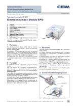
A detailed description of control, mounting and performance test of the Electropneumatic Module EPM can be found in “Assembly Instructions MA-E11". 1 Purpose The Electropneumatic Module EPM acts as interface between (electrical) power supply / control and pneumatic SITEMA clamping head. All pneumatic SITEMA clamping heads with an operating pressure up to 4 bar and an operating volume up to 220 cm3 can be pneumatically controlled by the EPM. (Other pressure levels and volumes can be provided upon request.) The EPM can be used where there is no stationary hydraulic or pneumatic system present and an electrical solution is required. 2 Function The EPM is controlled by a 24 V supply voltage and switching voltage. The outlet pressure which is required to actuate the pneumatic clamping head is controlled by the control signal (switching voltage) with the input command “apply pressure / release pressure”. If the voltage fails or the input signal is switched off, pressure is automatically released from the clamping head and the resulting (operating) condition is achieved. In order to monitor the proper function of the EPM, the output signal (alarm) can be integrated in the machine control. Depending on the type of the connected clamping head, different cycle times can be achieved. Cycle times of at least 2.5 Minutes should be obtained in all cases. 3 Structure The EPM consists of several components which produce an outlet pressure. An oil-free compressor produces pressure in a pressure accumulator. The outlet pressure is adjusted by a pressure control valve. An electromagnetic valve which can be controlled directly by the machine control pilots the outlet pressure. By applying 24 V between the input “switching voltage” and ground (“supply voltage GND”), the electromagnetic valve is energized and the SITEMA clamping head is pressurized. If the switching voltage is switched off, the electromagnetic valve moves to the initial position and the clamping head is depressurized. The air which is used for compression is absorbed through filters from the immediate environment. 4 Connection to clamping head SITEMA GmbH & Co. KG . G.-Braun-Stral3e 13 . D-76187 Karlsruhe . Phone: +49(0)721/98661-0 . Fax: -11 . www.sitema.com
Open the catalog to page 1
5 Technical Data 5.1 Electropneumatic Module EPM Type EPM 4 / ID no.: EPM 4 01 Subject to modification without prior notice The connection between EPM and clamping head requires the following parts : • pneumatic hose (external diameter: 4 mm, maximum length: 3 m) • optional: dump valve (size: see connection thread of pressure port at clamping head) • hose connector (e.g. push-in fitting; connector between pneumatic hose and clamping head or dump valve) We recommend our ready for use connection kit (see Chapter 5.2 “Connection kit”). 1 Pneumatic hose (external diameter: 4 mm, maximum length:...
Open the catalog to page 2
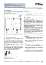
5.3 Dimensions The EPM can be mounted to the machine frame using the bore holes (threads: M 6) in the corners of the base plate. Mount the EPM in such a way that the electrical coupling can be reached and removed at any time. 6 Power requirement For the operation of the EPM a 24 V DC voltage is required. The maximum current can temporarily reach 8 A. The electrical supply and control unit needs to supply a DC voltage according to IEC 61010-1 (Chapters 6.3.1 and 6.3.2). The unit also needs to have a double separation / isolation from the power circuit according to IEC 61010-1...
Open the catalog to page 3
8 Operating conditions The immediate environment of the EPM in its standard version must be dry and clean. Especially moisture entering the EPM can cause equipment damage. Integrated air filters protect the pneumatic components from coarse particles in the intake air. The housing of the EPM consists of a polycarbonate plastic (PC). K Protect the EPM from contact with brake fluids, cooling lubricants, thinners and other media, which can lead to reactions with the housing material. Please contact SITEMA in case of heavy accumulation of contaminants. The EPM is not suitable for use in...
Open the catalog to page 4All SITEMA catalogs and technical brochures
-
PowerStroke SITEMA
9 Pages
-
SITEMA_Flyer_2020
2 Pages
-
TI-S10 Safety Locks
4 Pages
-
TI-A10
7 Pages
-
TI-P30
1 Pages
-
Dimensions, type KRG
1 Pages
-
Dimensions, type KRP/T
1 Pages
-
Dimensions, type KRP
1 Pages
-
Dimensions, type KR, K
2 Pages
-
SITEMA Safety Catchers
2 Pages
-
SITEMA Locking Units KFH
6 Pages
-
STB10 Rod Attachment STB
3 Pages
-
SITEMA Applications
2 Pages
-
F60 Dimensions, type KFHA
6 Pages
-
Z10 - Auto Bleeder
3 Pages
-
SITEMA Safety Locks KRG
1 Pages
-
SITEMA company
15 Pages
-
Locking Units KFPC
3 Pages
-
Locking units series KFPA
4 Pages


