- Catalogs
- SISTO Armaturen S.A.
- SISTO-SK-i LED
SISTO-SK-i LED
1 /22Pages

SISTO-SK-i LED
1 /22Pages
Catalog excerpts

Operating manual SISTO-SK-i LED SISTO-SK-i LED AS-i Intelligent Actual-position Feedback Unit for Linear Valves Stroke: 5 - 45 mm
Open the catalog to page 1
Glossary Type Series Booklet The Type Series Booklet can be downloaded at: http://sisto-aseptic.com/downloads/ or https://products.ksb.com/ SISTO-C LAP SISTO-C diaphragm valve with pneumatic piston actuator, stainless steel SISTO-C LAP.520 SISTO-C diaphragm valve with pneumatic piston actuator, stainless steel SISTO-C LAP.530 SISTO-C diaphragm valve with pneumatic piston actuator, aluminium, hard anodised SISTO-SK-i LED SISTO intelligent actual-position feedback unit SISTO-SK-i LED AS-i SISTO intelligent actual-position feedback unit with AS Interface
Open the catalog to page 3
This operating manual is aimed at the target group of trained and qualified specialist technical personnel. This operating manual does not take into account: • Any eventualities or incidents which may occur during installation, operation and maintenance performed by the customer. • Local regulations; the operator must ensure that such regulations are observed by all, including the personnel called in for installation. The operating manual must be kept for the entire life cycle of the equipment. For any queries you may have or in the case of damage, please contact SISTO Armaturen. ■ The actual-position...
Open the catalog to page 4
■ If the actual-position feedback unit is to be used in a damp environment, steps must be taken to ensure that any liquid that collects drains away from and does not penetrate the housing. ■ The unit must never be cleaned with a water jet and/or aggressive cleaning agents (observe the requirements of the type of enclosure Section 7.2, Page 8/Section 7.4, Page 10). ■ The housing of the actual-position feedback unit must not be subjected to mechanical loads. Connection and pneumatic lines must be routed in such a way that no forces act on the actual-position feedback unit. ■ Protect actual-position...
Open the catalog to page 5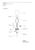
The actual-position feedback unit is marked with: ▪ Manufacturer ▪ Serial number ▪ Type Exploded view Printed circuit board (Elektronics) Stroke sensor (Elektronics) Slide (POM) Spring (Stainless steel) Bottom section (PA66GF30) (optional 1.4404) Socket (PBT) (model LAP.520 = PA) Rod (only for LAP.520) Not listed: Metal inserts 1.4404 NBR sealing eleme
Open the catalog to page 6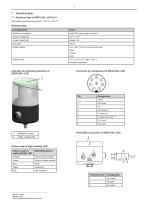
Permissible operating temperature: -30 °C to +60 °C Connector pin assignment of SISTO-SK-i LED Pin Colour code of high-visibility LED 3) With integrated solenoid valve only
Open the catalog to page 7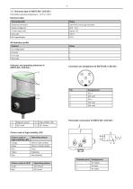
Permissible operating temperature: -30°C to +60°C Threaded port
Open the catalog to page 9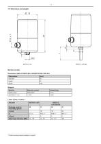
Mechanical data Dimensions table of SISTO-SK-i LED/SISTO-SK-i LED AS-i Dimensions Weights Material Material number Plastic, black Linear valves, variants 4) Actuator Ordering code for mounting options Further mounting variants available on request.
Open the catalog to page 11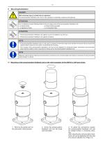
8.1 Mounting of the actual-position feedback unit on the valve actuators of the SISTO-C LAP type series: 1. Remove the guide bush on 2. Screw the actual-position 3. To adjust the connections exactly, the pneumatic valve actuator. feedback unit into the tread the actual-position feedback unit can and hand-tight. be rotated further in clockwise direc After adjusting the actual-position feedback unit can be tightened with the help of a wire pin (Section 8.3, Page 13).
Open the catalog to page 12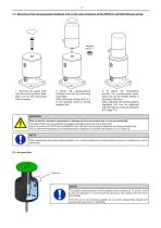
1. Remove the guide bush and the actual-position feedback unit on the pneumatic valve actuator. 2. Screw the actual-position feedback unit into the tread and hand-tight. With connection thread M18 x 1 in the actuator screw in thread adapter first. 3. To adjust the connections exactly, the actual-position feedback unit can be rotated further in clockwise direction. After adjusting the actual-position feedback unit can be tightened with the help of a wire pin (Section 8.3, Page 13). NOTE The bottom housing section and the adapter can be interlocked. To do this, insert a wire pin (diameter = 1 mm)...
Open the catalog to page 13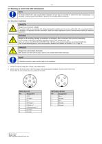
8.4 Mounting on valves from other manufactures On demand SISTO-SK-i LED actual-position feedback unit can also be mounted on valves from other manufactures. It is advisable to clarify the technical details in advance by consulting SISTO Armaturen. DANGER Danger from electrical voltage! The system must be de-energised and safeguarded against restarting and it must be verified that it is de-energised before it is accessed. All applicable accident prevention, health and safety regulations must be observed when working on electrical equipment. Danger to life resulting, damage to equipment or damage...
Open the catalog to page 14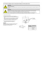
8.6 Pneumatic installation (only for actual-position feedback unit with solenoid valve) 1. Remove the screw plug. 2. Screw the hose connectors into the respective threaded connections on the actual-position feedback unit. (Hose connections are only included in the scope of delivery when an actual-position feedback unit with pneumatic valve actuator is ordered as a unit.) 3. Ensure that the threaded connections are established properly and are leak-free. Replace the silencer at threaded connection point 3 with a hose connector if the exhaust air is to be discharged via a connection line.
Open the catalog to page 15
9.1 Commissioning the actual-position feedback unit SISTO-SK-i LED/SISTO-SK-i LED AS-i without an integrated solenoid valve - on site 1. Verify that the electrical connections were established properly. 2. Check the supply voltage. 3. The valve actuator must be in its fail-safe position. 4. Check that the actual-position feedback unit is properly mounted on the valve actuator. Start initialisation: 1. Keep the programming magnet in the middle of the top of the cover for at least 2 seconds. If the colour code start flashing yellow, remove the magnet. 2. Activate the external solenoid valve to...
Open the catalog to page 16
1. Verify that the electrical and pneumatic connections were established properly. 2. Check the supply voltage and the control pressure present. 3. Check that the actual-position feedback unit is properly mounted on the valve actuator. Start initialisation: 1. Keep the programming magnet in the middle of the top of the cover for at least 2 seconds. If the colour code start flashing yellow, remove the magnet again. 2. The Actual-position feedback unit switches the internal solenoid valve, reaches the both limit positions and saves them internally. 3. Limit position will be saved and signalled...
Open the catalog to page 17All SISTO Armaturen S.A. catalogs and technical brochures
 SISTO_Company Flyer
4 Pages
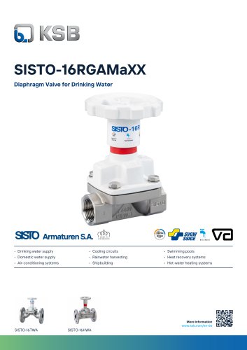
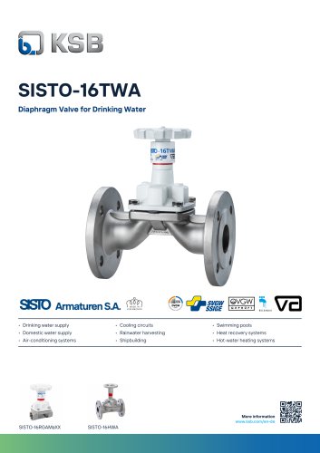 SISTO-16TWA_8660.026_11-EN
2 Pages
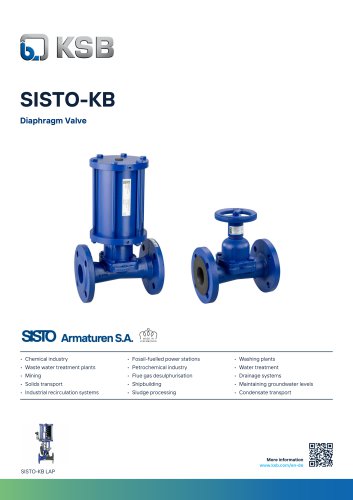 SISTO-KB_8651.023_04-EN
2 Pages
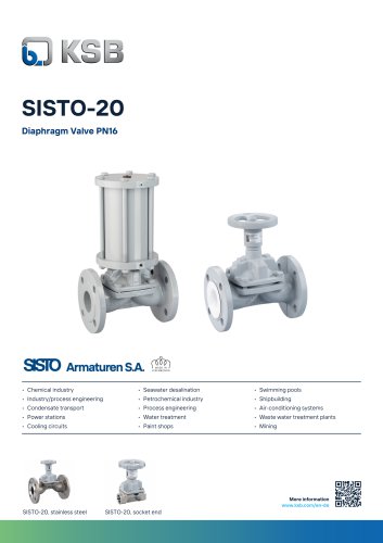 SISTO-20_8674.022_04-EN
2 Pages
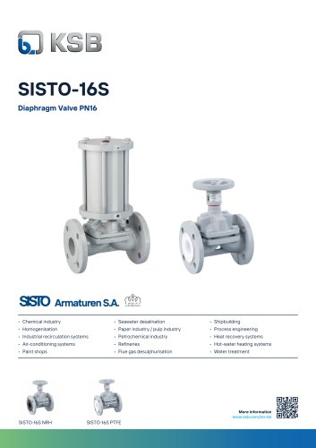 SISTO-16S_8635.024_01-EN
2 Pages
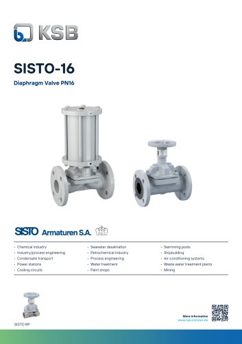 SISTO-16_8635.023_01-EN
2 Pages
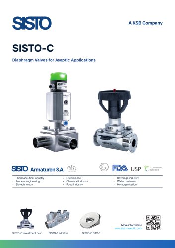 Flyer SISTO-C valves
2 Pages
- Accanto manual valve
- Control valve
- Accanto stainless steel valve
- Accanto water valve
- Threaded valve
- Flange valve
- Accanto shut-off valve
- Flap valve
- Accanto electric actuator
- Check valve
- Electric valve
- ISO valve
- Gas valve
- Accanto valve with handwheel
- Pneumatically-operated valve
- Valve for industrial applications
- Valve for the chemical industry