Mini M135 & M145
1 /2Pages

Mini M135 & M145
1 /2Pages
Catalog excerpts

Mini M135 & M145 Digital Panel Meters Specifications Type Height Most significant = “1” other digits blank • Snaps right into panel - no mounting hardware required Overrange Indication • Minimum depth - requires less than 0.7” (17mm) behind the panel Decimal Point Position Optional negative image, red backlighting at 5, 10. 12, 24 or 48 DCV Auto with “-” indication, “+” indication implied POWER REQUIREMENTS ±5V, +5V and +9V Low Power Indication included with 9V units Power supply current Backlight supply current Input Specifications 3 1/2 digit: ± (0.1% of reading + 1 count) Input Impedance 4 1/2 digit: ± (0.04% of reading + 1 count) Voltage Drop Warmup time Less than 20 minutes Temperature Coefficient (All inputs) ± (0.02% of input ± 0.2 digit) / °C Storage Temperature Relative Humidity ENVIRONMENTAL Operating Temperature NOISE REJECTION NMRR MECHANICAL Bezel Panel cutout Case Material
Open the catalog to page 1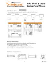
Mini M135 & M145 Digital Panel Meters Ordering Information - Clear Order Form Mini indicators can be configured by making an entry in each section below. Example: M135-0-2-11-0 Basic Unit Function/ Range Backlight Power Select From Each One Below Select From Each One Below Basic Unit Function / Range Backlight Power Negative Read Backlight Mounting Requirements The Mini indicators require a panel cutout of 2.71” (68.8mm) wide by 0.89” (22.6mm) high, and a panel area of 0.94” (24mm) high by 2.83” (72mm) wide. The depth behind the panel, including terminals, is 0.7” (17.8mm). The front bezel protrudes...
Open the catalog to page 2All Simpson catalogs and technical brochures
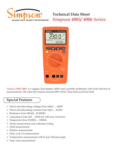 Simpson 4005/ 4006 Series
8 Pages
 Wide-Vue
10 Pages
 S660 Totalizer/Counter
5 Pages
 Amik 200
8 Pages
 Amik 100
6 Pages
 Test Equipment Catalog
29 Pages
 GIMA Series
2 Pages
 2800 Series
2 Pages
 Falcon F35 & F45
3 Pages
 MiniMax M240
2 Pages
 mini-max M235 - M245
3 Pages

Archived catalogs
 Test Equipment Catalog
29 Pages
 SE Encoders
1 Page
 GIMA Digital Panel Meters
3 Pages
 Panel Instrument Catalog
68 Pages
- Transformer
- Rototherm measuring instrument
- Dry transformer
- Calibration system
- Digital indicator
- Portable tester
- Panel panel meter
- Current transformer
- Industrial tester
- Digital gauge
- Multimeter
- Voltage testing system
- Digital multimeter
- Portable multimeter
- Instrument transformer
- Digital counter
- Analog indicator
- Process panel meter
- Industrial multimeter
- Compact tester