
- Catalogs
- Silicon Laboratories
- Si8600/Si8602/Si8605/Si8606 Bidirectional I2C Isolators with Unidirectional Digital Channels


- Products
- Catalogs
- News & Trends
- Exhibitions
Si8600/Si8602/Si8605/Si8606 Bidirectional I2C Isolators with Unidirectional Digital Channels
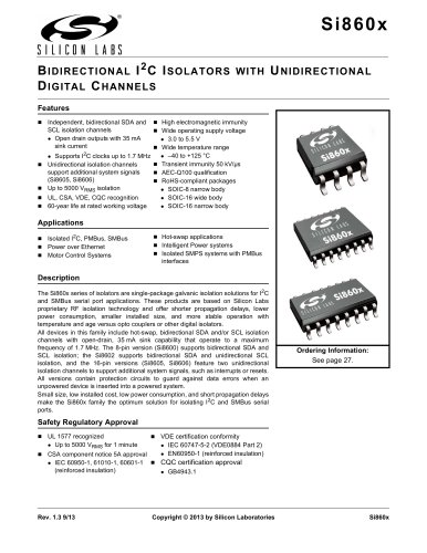
Si8600/Si8602/Si8605/Si8606 Bidirectional I2C Isolators with Unidirectional Digital Channels
- Bidirectional SDA and SCL isolation channels with open-drain outputs supporting up to 1.7 MHz frequency.
- Unidirectional isolation channels for additional signals like interrupts or resets.
- High safety standards with up to 5000 VRMS isolation and certifications from UL, CSA, VDE, and CQC.
- Wide operating voltage range (3.0 to 5.5 V) and temperature range (-40 to +125 °C).
- High electromagnetic and transient immunity of 50 kV/µs.
- Operating temperature range from -40 to +125 °C.
- Supply voltage range from 3.0 to 5.5 V.
- Various current consumption specifications depending on the model and operating conditions.
- Use a 0.1 µF bypass capacitor for supply bypassing.
- Consider series resistors for noise reduction in noisy systems.
- Ensure compliance with end-system specifications for safety and isolation requirements.
- Tables provide ratings for basic isolation and insulation characteristics, safety limiting values, and absolute maximum ratings.
- Figures illustrate thermal derating curves for different package types.
Catalog excerpts

Si860x B IDIRECTIONAL I 2 C I SOLA TORS WITH U NIDIRECTIONAL D IGITA L C HANNELS Features Independent, bidirectional SDA and SCL isolation channels Open drain outputs with 35 mA sink current High electromagnetic immunity Wide operating supply voltage 3.0 Wide temperature range –40 to +125 °C I2C clocks up to 1.7 MHz Transient immunity 50 kV/µs Unidirectional isolation channels support additional system signals AEC-Q100 qualification (Si8605, Si8606) RoHS-compliant packages Up to 5000 VRMS isolation SOIC-8 narrow body SOIC-16 wide body UL, CSA, VDE, CQC recognition SOIC-16 narrow body 60-year life at rated working voltage Supports Applications Isolated I2C, PMBus, SMBus Power over Ethernet Motor Control Systems Hot-swap applications Intelligent Power systems Isolated SMPS systems with PMBus Description The Si860x series of isolators are single-package galvanic isolation solutions for I2C and SMBus serial port applications. These products are based on Silicon Labs proprietary RF isolation technology and offer shorter propagation delays, lower power consumption, smaller installed size, and more stable operation with temperature and age versus opto couplers or other digital isolators. All devices in this family include hot-swap, bidirectional SDA and/or SCL isolation channels with open-drain, 35 mA sink capability that operate to a maximum frequency of 1.7 MHz. The 8-pin version (Si8600) supports bidirectional SDA and SCL isolation; the Si8602 supports bidirectional SDA and unidirectional SCL isolation, and the 16-pin versions (Si8605, Si8606) feature two unidirectional isolation channels to support additional system signals, such as interrupts or resets. All versions contain protection circuits to guard against data errors when an unpowered device is inserted into a powered system. Small size, low installed cost, low power consumption, and short propagation delays make the Si860x family the optimum solution for isolating I2C and SMBus serial ports. Ordering Information: See page 27. Safety Regulatory Approval UL 1577 recognized Up to 5000 VRMS for 1 minute CSA component notice 5A approval CQC certification approval IEC 60950-1, 61010-1, 60601-1 (reinforced insulation) GB4943.1 VDE certification conformity IEC 60747-5-2 (VDE0884 Part 2) EN60950-1 (reinforced insulation) Copyright © 2013 by Silicon Laboratories
Open the catalog to page 1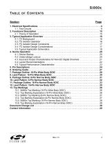
Si860x TABLE O F C ONTENTS Section 1. Electrical Specifications . . . . . . . . . . . . . . . . . . . . . . . . . . . . . . . . . . . . . . . . . . . . . . . . . . .4 1.1. Test Circuits . . . . . . . . . . . . . . . . . . . . . . . . . . . . . . . . . . . . . . . . . . . . . . . . . . . . . . . .9 2. Functional Description . . . . . . . . . . . . . . . . . . . . . . . . . . . . . . . . . . . . . . . . . . . . . . . . . . . 15 2.1. Theory of Operation . . . . . . . . . . . . . . . . . . . . . . . . . . . . . . . . . . . . . . . . . . . . . . . . . 15 3. Typical Application Overview . . . . . ....
Open the catalog to page 3
Si860x 1. Electrical Specifications Table 1. Recommended Operating Conditions Symbol Ambient Operating Temperature* Supply Voltage *Note: The maximum ambient temperature is dependent on data frequency, output loading, number of operating channels, and supply voltage. Table 2. Si860x Power Characteristics* 3.0 V < VDD < 5.5 V. TA = –40 to +125 °C. Typical specs at 25 °C (See Figures 2 and 10 for test diagrams.) Test Condition AVDD Current BVDD Current Idda Iddb AVDD Current BVDD Current Idda Iddb AVDD Current BVDD Current Idda Iddb AVDD Current BVDD Current Idda Iddb AVDD Current BVDD Current...
Open the catalog to page 4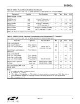
Si860x Table 2. Si860x Power Characteristics* (Continued) 3.0 V < VDD < 5.5 V. TA = –40 to +125 °C. Typical specs at 25 °C (See Figures 2 and 10 for test diagrams.) Test Condition AVDD Current BVDD Current Idda Iddb AVDD Current BVDD Current Idda Iddb AVDD Current BVDD Current Idda Iddb *Note: All voltages are relative to respective ground. Table 3. Si8600/02/05/06 Electrical Characteristics for Bidirectional I2C Channels1 3.0 V < VDD < 5.5 V. TA = –40 to +125 °C. Typical specs at 25 °C unless otherwise noted. Logic Levels Side B Logic Low Input Voltage Logic High Input Voltage Logic Low Output...
Open the catalog to page 5
Si860x Table 3. Si8600/02/05/06 Electrical Characteristics for Bidirectional I2C Channels1 (Continued) 3.0 V < VDD < 5.5 V. TA = –40 to +125 °C. Typical specs at 25 °C unless otherwise noted. Test Condition Timing Specifications (Measured at 1.40 V Unless Otherwise Specified) Maximum I2C Bus Frequency Propagation Delay 5 V Operation Side A to Side B Rising4 Side A to Side B Falling4 Side B to Side A Rising Side B to Side A Falling 3.3 V Operation Side A to Side B Rising4 Side A to Side B Falling4 Side B to Side A Rising Side B to Side A Falling Pulse Width Distortion 5V Side A Low to Side B Low4...
Open the catalog to page 6
Si860x Table 4. Electrical Characteristics for Unidirectional Non-I2C Digital Channels (Si8602/05/06) 3.0 V < VDD < 5.5 V. TA = –40 to +125 °C. Typical specs at 25 °C Test Condition Positive-Going Input Threshold Negative-Going Input Threshold Input Hysteresis High Level Input Voltage Low Level Input Voltage High Level Output Voltage Low Level Output Voltage Maximum Data Rate Minimum Pulse Width Input Leakage Current 1 Output Impedance Timing Characteristics Propagation Delay Pulse Width Distortion |tPLH – tPHL| Propagation Delay Skew2 Channel-Channel Skew tPHL, tPLH Output Rise Time Output Fall...
Open the catalog to page 7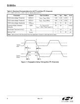
Si860x Table 5. Electrical Characteristics for All I2C and Non-I2C Channels 3.0 V < VDD < 5.5 V. TA = –40 to +125 °C. Typical specs at 25 °C Test Condition Common Mode Transient Immunity Shut Down Time from UVLO Start-up Time *Note: Start-up time is the time period from the application of power to valid data at the output. Figure 1. Propagation Delay Timing (Non-I2C Channels)
Open the catalog to page 8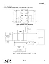
Si860x 1.1. Test Circuits Figure 2 depicts the timing test diagram; Figure 3 depicts the CMTI test diagram. Figure 2. Simplified Timing Test Diagram Input Signal Switch 3 to 5 V Isolated Supply Isolated Ground Input High Voltage Differential Probe Vcm Surge Output High Voltage Surge Generator Figure 3. Common Mode Transient Immunity Test Circuit
Open the catalog to page 9All Silicon Laboratories catalogs and technical brochures
 ISOmodem Solutions Guide
2 Pages
 PRODUCT SELECTOR GUIDE 2013
36 Pages
 MCU Selector Guide
20 Pages
 Wireless and RF Selector Guide
12 Pages
 Human Interface Solutions Guide
12 Pages
 Isolation Selector Guide
10 Pages
 Microcontroller Selector Guide
20 Pages
 Audio Applications Guide
24 Pages
 USB Bridge Solutions
2 Pages
 Si4032/31/30 ISM Transmitter
2 Pages







Archived catalogs
 Broadcast Audio Solutions
2 Pages
 Digital Power Solutions
2 Pages
 Low-Voltage/Low-Power MCUs
2 Pages


- Temperature probe
- Proximity switch
- Transceiver module
- Rectangular proximity sensor
- Crystal oscillator
- Radio transceiver module
- Surface-mount oscillator
- Digital proximity sensor
- Semiconductor temperature sensor
- Electromechanical oscillator
- IC transceiver
- Gate driver
- Silicon temperature sensor
- Signal isolator-converter
- FM transceiver
- Infrared proximity sensor
- MOSFET gate driver
- Isolator signal isolator-converter
- IC temperature sensor
- AM/FM tuner