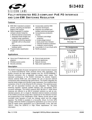
Catalog excerpts
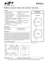
Pin Assignments:See page20 Single-chip ac current sensor/conditioner FAULT output helps safeguard operation Low loss: Less than 1.3 m 1,000VDC isolation primary series resistance; less than 2nH primary inductance at 25C Accurate to ڱ5% of measurement 12-Pin QFN Large 2V > PP output pins signal at full scale Leading-edge noise suppression eliminates need for leading-edge blanking High-side or low-side current sensing > R1R2GND2GND3OUTNC 1 IINIOUT "Ping-Pong" output version allows one Si85xx to replace two current transformers in full-bridge applications 40 to 125 ֺC operating range (Si85x4/5/6) > Small 4x4x1mm package Low cost 5, 10, and 20A full-scale versions > TRSTGND1VDD2VDD1 Power supplies Lighting equipment Motor controls Industrial equipment > R1R2R3R4OUT1OUT2 1 IINIOUT The Si85xx products are unidirectional ac current sensors available in full-scale ranges of 5, 10, and 20A. Si85xx products are ideal upgrades forolder current-sensing technologies offering size, performance and costadvantages over current transformers, Hall effect devices, DCR circuitsand other approaches. The Si85xx are extremely low loss, adding lessthan 1.3m > of series resistance and less than 2nH series inductance inthe sensing path at 25C. Current-sensing terminals are isolated from theother package pins to a maximum voltage of 1,000VDC. > TRST/FAULTGNDMODEVDD Patents pending > R1 R2 R3 R4 Si851x VDD RESET LOGIC MODE LOGIC MODE TRST IINIOUT R2 GND1 Si850x OUT1 INTEGRATOR SIGNAL CONDITIONING GND2 VIN OUT2 PH1PH2 R1OUTVDD1 Q1Q2 METAL SLUG L VOUT C TEMP SENSOR ADC AUTO CALIBRATION LOGIC Typical Application GND VDDTRST/FAULTIOUT IIN Preliminary Rev. 0.1 7/07Copyright ک 2007 by Silicon LaboratoriesSi85xx This information applies to a product under development. Its characteristics and specifications are subject to change without notice.Silicon Laboratories Confidential. Information contained herein is covered under non-disclosure agreement (NDA). size="-2">
Open the catalog to page 1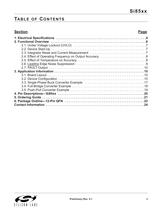
1. Electrical Specifications . . . . . . . . . . . . . . . . . . . . . . . . . . . . . . . . . . . . . . . . . . . . . . . . . . .42. Functional Overview . . . . . . . . . . . . . . . . . . . . . . . . . . . . . . . . . . . . . . . . . . . . . . . . . . . . . .6 2.1. Under Voltage Lockout (UVLO) . . . . . . . . . . . . . . . . . . . . . . . . . . . . . . . . . . . . . . . . .7 2.2. Device Start-Up . . . . . . . . . . . . . . . . . . . . . . . . . . . . . . . . . . . . . . . . . . . . . . . . . . . . . .72.3. Integrator Reset and Current Measurement . . . . . . . . . . . . . . . . . . . . ....
Open the catalog to page 3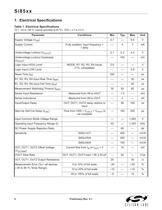
TA = 40 to +85 ֺC (typical specified at 25 C), VDD = 2.7 to 5.5V Parameter Conditions Min Typ Max Unit Supply Voltage (V > DD ) 2.7 ڗ 5.5 V Supply Current Fully enabled, input frequency = 1MHz 4 7 mA Undervoltage Lockout (V > UVLO ) 2.1 2.3 2.5 V Undervoltage Lockout Hysteresis (V ח 100 mV > HYST ) Logic Input HIGH Level MODE, R1, R2, R3, R4 inputs (TTL compatible) 2.0 ח V Logic Input LOW Level ח 0.8 V Reset Time (t > R ) 250 ח ns R1, R2, R3, R4 Input Rise Time (t > RR ) ח 30 ns R1, R2, R3, R4 Input Fall Time (t > FR ) ח 30 ns Measurement Watchdog Timeout (t > WD ) 30 50 80 s Series Input...
Open the catalog to page 4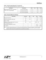
TA = 40 to +85 ֺC (typical specified at 25 C), VDD = 2.7 to 5.5V Parameter Conditions Min Typ Max Unit Measurement Error (%)ڗall devices(40 to 125ֺC Temp Range) 5 to 10% of full scale 30 ֗ +30 % 10 to 20% of full scale 25 ֗ +25 % 20 to 100% of full scale 20 ֗ +20 % > ParameterSymbolMinTypMaxUnits Storage temperatureT > STG 65+150ֺCAmbient temperature under biasT > A 40+125ֺCSupply voltageV > DD 5.75VVoltage on any pin with respect to ground (not including IIN, IOUT) V > IN 0.5VDD + 0.5VLead solder temperature (10 sec.)-260ֺCDC isolation -1000VDC > Note: Permanent device damage may occur if...
Open the catalog to page 5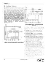
The Si85xx AC Current Sensor family of products mimicthe functionality of a traditional current transformer (CT)circuit with burden resistor, diode and output filter, butoffers enhanced performance and added capabilities.These devices use inductive current sensing and on-board signal conditioning electronics to generate a 2V full-scale output signal proportional to the ac currentflowing from the IIN to the IOUT terminals. As shown in Figure1 and Figure2, current flowing through the metalpackage slug induces a signal in the pickup coil on-board the Si85xx die. This signal is applied to the...
Open the catalog to page 6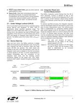
FAULT output (Si8517/8/9): goes low when external reset timing is in error. > Ease-of-use: Other than conventional power and grounding techniques, no special board layout considerations are required. Built-in timing interface circuits allow already available system switching signals to be used for resetno external circuits required. The Si85xx measures current flowing from the IIN toIOUT terminals. Current is allowed to flow in the opposite direction, but will not be measured (OUT1 andOUT 2 remain at their minimum values during reversecurrent flow. Reverse current flow will not damage the...
Open the catalog to page 7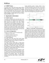
2-wire Ping-Pong mode is useful mainly in non-overlapping two-phase buck converters, but may alsobe used in full-bridge applications. In this output mode,reset inputs R1 and R2 are used, and input R3 isgrounded. Measured current appears on OUT1 whenR2 is high, and appears on OUT2 when R1 is high asshown in the full-bridge timing example of Figure9. > The FAULT output (Si8517/8/9) guards against Si85xxoutput signal errors caused by missing reset cycles.FAULT is asserted when a measurement cycle exceedsthe internal watchdog timer times limit of t > WD . FAULT can be used to alert a local...
Open the catalog to page 10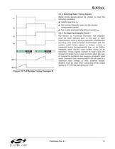
3.2.2. Selecting Reset Timing Signals Reset timing signals should be chosen to meet thefollowing conditions: > R1 R3R2 R4 Satisfy reset time t > R Not overlap integrator reset into the desired measurement period Not violate reset watchdog timeout period t > WD 3.2.3. Configuring Integrator Reset Per Section 2. Functional OverviewӔ, the integratormust be reset (zeroed) prior to the start of each measurement cycle to achieve specified measurementaccuracy. This reset must be synchronized with the system switch timing signals to ensure current is measured during the appropriate time, so the...
Open the catalog to page 11All Silicon Laboratories catalogs and technical brochures
-
ISOmodem Solutions Guide
2 Pages
-
PRODUCT SELECTOR GUIDE 2013
36 Pages
-
MCU Selector Guide
20 Pages
-
Wireless and RF Selector Guide
12 Pages
-
Human Interface Solutions Guide
12 Pages
-
Isolation Selector Guide
10 Pages
-
Microcontroller Selector Guide
20 Pages
-
Audio Applications Guide
24 Pages
-
USB Bridge Solutions
2 Pages
-
Si4032/31/30 ISM Transmitter
2 Pages
Archived catalogs
-
Broadcast Audio Solutions
2 Pages
-
Digital Power Solutions
2 Pages
-
Low-Voltage/Low-Power MCUs
2 Pages


